


O
r
a
n
g
e
Y
e
l
l
o
w
B
l
u
e
B
l
a
c
k
B
r
o
w
n
R
e
d
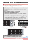
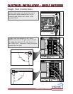
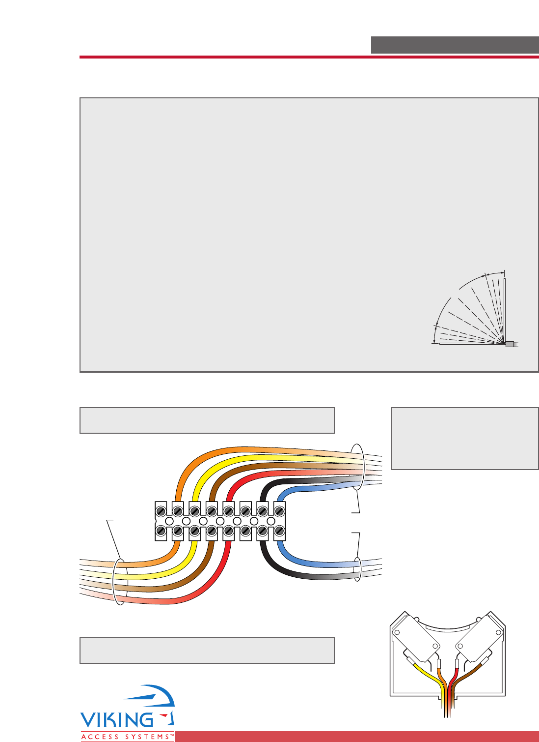
To Limit
Switches
To Motor
Wire Lead
From Control Box
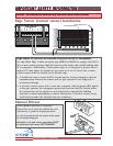
TECHNICAL SUPPORT 1 800 908 0884
15
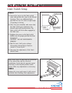
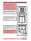
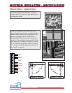
The Limit Switches are wired as shown
Limit Switch Connections
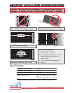
NC
N0
COM
NC
N0
COM
Yellow
Orange
Brown
Red
Connect the lead wires as shown
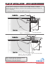
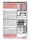
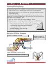
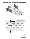
To have the gate operator slow down prior to reaching its limits use the following steps:
1. Setup the limit switches manually at the desired open and close position.
2. Allow the gate operator to run a full open and close cycle (from limit to limit)
without interruption.
Note: During the first full open and close cycle: The gate operator doesn’t slow
down prior to reaching its limits. During subsequent cycles: The gate operator will
slow down prior to reaching its limits.
3. Verify that the gate opens and closes to the desired position.
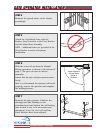
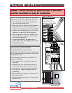
To change the open or close limit position(s) the following steps MUST BE taken:
A.Reset the gate operator by performing one of the following steps:
i. Disconnect the Power Harness Connector (see page 17) or
ii. Disconnect the Motor/Limit Harness Connector
(see page 18 or 19) or
iii.Actuate both limits at the same time
B. Repeat steps 1,2 and 3.
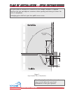
Reference Wiring Diagram
Opening/Closing Setup:
GATE OPERATOR INSTALLATIONGATE OPERATOR INSTALLATION
Fast
Slow
Slow
Note: Use this wiring
diagram as a guide to
connect the wires to the
motor unit.