


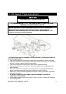
12.1 Power Connection:
A
A
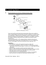
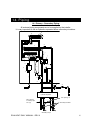
Figure 12.1
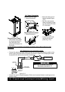
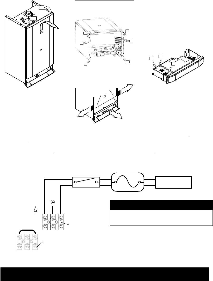
Removing Front Panel:
• Remove the front panel
by removing screws A
and sliding the front
panel up and away from
the boiler
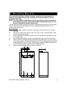
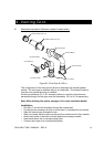
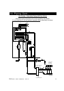
Removing Side Panel:
• Remove screws B
B
B
C
C
B
B
Figure 12.2
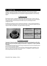
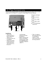
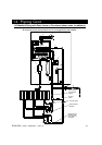
Removing Control Panel:
• Remove screws C.
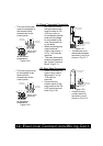
Figure 12.3
• Move the lower part of
the side panels (figure
12.3).
• Pull the control panel.
When completely pulled
out, the panel can rotate
45° downward.
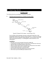
D
D
D
Figure 12.4
• Loosen screws D and
remove the service
panel (Fig. 12.4).
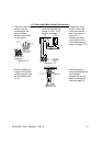
For the electrical connection to the boiler use electric wires which conform to local
regulations.
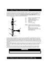
12.2 Connection to the electricity supply:
• Connect the electrical supply cable coming from the fused spur isolation switch to the
power supply terminal block of the boiler (as shown in figure 12.5) keeping the same
connections for the live wire and the neutral wire.
12
L
N
3
To fused spur
isolation switch
Power supply
terminal block
External controls
terminal block
120 VAC
15 AMP BREAKER
Service Man's Switch
Fire - O - Matic
23
Figure 12.5
• Connect the earth wire(yellow/green). Boiler must be wired directly to earth ground on
breaker panel.
Note: Do not connect live wires to
thermostat terminals 1-3.
W
ARNING
RIVA HEAT ONLY MANUAL - REV A
12. Electrical Connections/Wiring Cont.