


8 18-CD21D1-5
Installer’s Guide
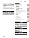
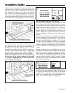
If the furnace is suspended using perforated steel strap
(plumber’s strap), it must be supported at all four cor-
ners and in the middle at the front of the furnace.
The forward most screw on the side of the furnace
may be used to connect the strapping (See Figure 6).
Line contact is only permissible between lines formed
by the intersection of the top and two sides of the fur-
nace casing and the building joists, studs, or framing.
A cutout is provided on both sides of the downflow fur-
nace cabinet to allow a 90° elbow to be attached inside
the cabinet and the vent piping to connect there. In
horizontal, the downflow furnace may be vented
through the top of the cabinet if needed. In vertical con-
figuration, the downflow furnace may be vented using
the side cabinet cutouts. This venting configuration
could be used if an electronic air cleaner is installed.
When the downflow furnace is vented through
the left side of the furnace cabinet in horizontal
or vertical configuration, Type B vent pipe must
be used within the cabinet.
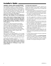
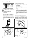
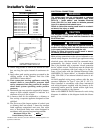
Confined spaces are installations with less than 50 cu.
ft. of space per 1000 BTU/ hr input from all equipment
installed. Air for combustion and ventilation require-
ments can be supplied from inside the building as in
Figure 9 or from the outdoors, as in Figure 10.
AIR FOR COMBUSTION AND VENTILATION
Adequate flow of combustion and ventilating air must
not be obstructed from reaching the furnace. Air open-
ings provided in the furnace casing must be kept free of
obstructions which restrict the flow of air. Airflow re-
strictions affect the efficiency and safe operation of the
furnace. Keep this in mind should you choose to re-
model or change the area which contains your furnace.
Furnaces must have a free flow of air for proper perfor-
mance.
Provisions for combustion and ventilation air shall be
made in accordance with “latest edition” of Section 5.3,
Air for Combustion and Ventilation, of the National
Fuel Gas Code, ANSI Z223.1, or Sections 7.2, 7.3 or 7.4
of CAN/ CGA B149 Installation Codes, and applicable
provisions of the local building codes. Special conditions
created by mechanical exhausting of air and fireplaces
must be considered to avoid unsatisfactory furnace op-
eration.
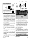
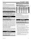
Furnace locations may be in “confined space” or “uncon-
fined space”. Unconfined space is defined in Table 2 and
Figure 7. These spaces may have adequate air by infiltra-
tion to provide air for combustion, ventilation, and dilu-
tion of flue gases. Buildings with tight construction (for
example, weather stripping, heavily insulated, caulked,
vapor barrier, etc.), may need additional air provided as
described for confined space.
5
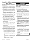
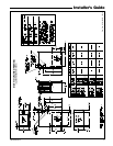
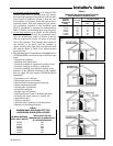
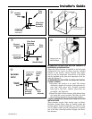
TYPICAL ATTIC PLATFORM INSTALLATION
(UPFLOW/HORIZONTAL FURNACE SHOWN)
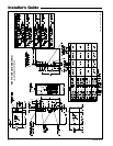
Typical Suspended Installation
(Upflow/Horizontal Furnace Shown)
6
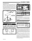
50 CU. FT. OR MORE
PER 1000 BTU/ HR.
INPUT ALL EQUIP-
MENT INSTALLED
UNCONFINED
7
CONFINED
8
LESS THAN 50 CU. FT.
PER 1000 BTU/ HR.
INPUT ALL EQUIP-
MENT INSTALLED