


10 18-CD21D1-5
Installer’s Guide
DUCT CONNECTIONS
Air duct systems should be installed in accordance with
standards for air conditioning systems, National Fire
Protection Association Pamphlet No. 90. They should
be sized in accordance with ACCA Manual D or which-
ever is applicable. Check on controls to make certain
they are correct for the electrical supply.
Central furnaces, when used in connection with cooling
units, shall be installed in parallel or on the upstream
side of the cooling units to avoid condensation in the
heating element, unless the furnace has been specifi-
cally approved for downstream installation. With a par-
allel flow arrangement, the dampers or other means
used to control flow of air shall be adequate to prevent
chilled air from entering the furnace, and if manually
operated, must be equipped with means to prevent op-
eration of either unit unless the damper is in full heat
or cool position.
On any job, flexible connections of nonflammable ma-
terial may be used for return air and discharge con-
nections to prevent transmission of vibration.
Though these units have been specifically designed
for quiet, vibration free operation, air ducts can act
as sounding boards and could, if poorly installed, am-
plify the slightest vibration to the annoyance level.
When the furnace is located in a utility room adjacent
to the living area, the system should be carefully de-
signed with returns which minimize noise transmission
through the return air grille. Although these winter air
conditioners are designed with large blowers operating
at moderate speeds, any blower moving a high volume
of air will produce audible noise which could be objec-
tionable when the unit is located very close to a living
area. It is often advisable to route the return air ducts
under the floor or through the attic. Such design per-
mits the installation of air return remote from the liv-
ing area (i.e. central hall).
When the furnace is installed so that the supply ducts
carry air circulated by the furnace to areas outside the
space containing the furnace, the return air shall also
be handled by a duct(s) sealed to the furnace and termi-
nating outside the space containing the furnace.
Minimum return air “entering temperature” for
the furnace is 55° F.
Where there is no complete return duct system, the re-
turn connection must be run full size from the furnace
to a location outside the utility room, basement, attic,
or crawl space.
DO NOT install return air through the back of the
furnace cabinet.
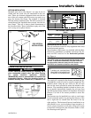
RETURN AIR DUCT CONNECTION
NOTE:
On upflow 5 or 6 ton airflow models, if the airflow re-
quirement exceeds 1800 CFM, these models will re-
quire return air openings and filters on both sides; OR
1 side and the bottom; OR just the bottom.
▲
WARNING
!
TO PREVENT INJURY OR DEATH DUE TO CONTACT
WITH MOVING PARTS, TURN THE POWER TO THE
FURNACE OFF BEFORE SERVICING FILTERS.
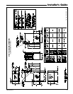
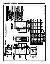
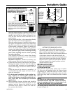
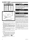
4. The side panels of the upflow furnace include
locating notches that are used as guides for cutting
an opening for return air, refer to Figure 12 and the
outline drawing on page 5 for duct connection
dimensions for various furnaces.
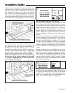
5. If a 3/4" flange is to be used for attaching the air in-
let duct, add to cut where indicated by solid lines
in Figure 12. Cut corners diagonally and bend out-
ward to form flange.
6. If flanges are not required, and a filter frame is in-
stalled, cut between the locating notches. See
Figure 12.
7. Upflow Furnaces: a filter rack is factory supplied
for bottom or side return. Use the filter rack on ei-
ther side or on the bottom if the filter is to be used
within the furnace cabinet.
▲
WARNING
!
Do NOT install the filter in the return duct directly
above the furnace in horizontal applications. Install
the filter remotely. Installing the filter directly above
the furnace in horizontal applications may cause
property damage, serious injury or death.
All return air duct systems should provide for installa-
tion of return air filters.
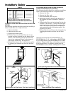
PREPARATION FOR UPFLOW BOTTOM AND SIDE
RETURN AIR FILTER INSTALLATION
All return air duct systems should provide for installa-
tion of return air filters.
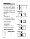
1. Determine the appropriate postion to set the
furnace in order to connect to the supply and return
ductwork.
2. The return air filter and rack are shipped in either
the bottom or side location. Remove the filter and
filter rack by first turning the two latches on the
blower door and tilting the door forward to remove.
Remove the filter by sliding it out of the rack.
Compress the spring loaded filter rack to disengage
the retaining pins/screws from the furnace sides
and slide the filter rack out.
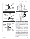
The filter rails are spring loaded for automatic
adjustment to allow standard size, locally obtainable
replacement filters. The filter rack itself slides to
adjust to the required width needed for bottom or
side return.
3. For upflow side return installations, remove the
insulation around the opening in the blower compart-
ment.