


16 18-CD21D1-5
Installer’s Guide
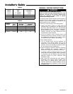
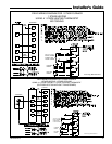
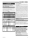
TABLE 8
ππ
ππ
π(D*)
2
4
= X 7
8. Where long periods of airflow are desired for com-
fort, use long fan cycles instead of continuous air-
flow.
9. Apply other good venting practices as stated in the
venting section of the National Fuel Gas Code
ANSI Z223.1 “latest edition”.
10. Vent connectors serving appliance vented by
natural draft or non-positive pressure shall
not be connected into any portion of a mecha-
nized draft system operating under positive
pressure.
11. Horizontal pipe runs must be supported by hangers,
straps or other suitable material in intervals at a
minimum of every 3 feet of pipe.
12. A furnace shall not be connected to a chimney or
flue serving a separate appliance designed to burn
solid fuel.
13. The flow area of the largest section of vertical vent
or chimney shall not exceed 7 times the smallest
listed appliance categorized vent area, flue collar
area, or draft hood outlet area unless designed in
accordance with approved engineering methods.
Maximum Vent or Tile
Lined Chimney Flow Area
*Drafthood outlet diameter, flue collar diameter, or listed appliance cat-
egorized vent diameter.
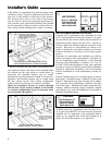
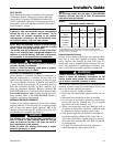
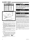
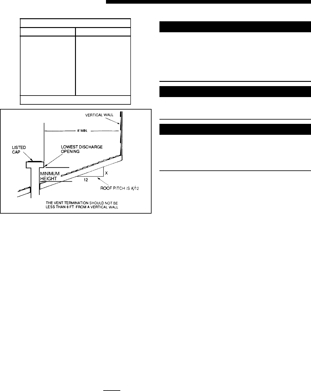
GAS VENT TERMINATION
ROOF PITCH MINIMUM HEIGHT
FLAT TO 7/12
OVER 7/12 TO 8/12
OVER 8/12 TO 9/12
OVER 9/12 TO 10/12
OVER 10/12 TO 11/12
OVER 11/12 TO 12/12
OVER 12/12 TO 14/12
OVER 14/12 TO 16/12
OVER 16/12 TO 18/12
OVER 18/12 TO 20/12
OVER 20/12 TO 22/12
1.0 FEET *
1.5 FEET
2.0 FEET
2.5 FEET
3.25 FEET
4.0 FEET
5.0 FEET
6.0 FEET
7.0 FEET
7.5 FEET
8.0 FEET
* THIS REQUIREMENT COVERS MOST INSTALLATIONS
d
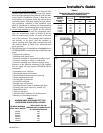
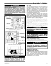
ELECTRICAL CONNECTIONS
▲
WARNING
!
The cabinet must have an uninterrupted or unbroken
ground according to National Electrical Code, ANSI/
NFPA 70 – “latest edition” and Canadian Electrical
Code, CSA C22.1 or local codes to minimize personal
injury if an electrical fault should occur.
Failure to follow this warning could result in an electri-
cal shock, fire, injury, or death.
▲
CAUTION
!
The integrated furnace control is polarity sensitive. The
hot leg of the 115 VAC power must be connected to the
BLACK field lead.
▲
WARNING
!
To prevent injury or death due to electrical shock or
contact with moving parts, lock unit disconnect switch
in the open position before servicing the unit.
Failure to follow this warning could result in electri-
cal shock, personal injury, or death.
Make wiring connections to the unit as indicated on en-
closed wiring diagram. As with all gas appliances using
electrical power, this furnace shall be connected into a
permanently live electric circuit. It is recommended
that it be provided with a separate “circuit protection
device” electric circuit. The furnace must be electrically
grounded in accordance with local codes or in the ab-
sence of local codes with the National Electrical Code,
ANSI/NFPA 70 “latest edition” or Canadian Electrical
Code, CSA C22.1, if an external electrical source is uti-
lized.
All field supplied wiring must conform with the tem-
perature limitation for Type T wire [63° F. (35° C)],
when installed in accordance with these instructions
and wiring diagrams supplied with the furnace. A dis-
connecting means must be located within sight from,
and readily accessible to, the furnace.
Refer to the SERVICE FACTS literature for unit wiring
diagrams in addition to the diagram inside the blower
door.