


4 18-CD21D1-5
Installer’s Guide
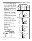
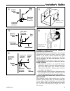
LOCATION AND CLEARANCES
The location of the furnace is normally selected by the
architect, the builder, or the installer. However, before
the furnace is moved into place, be sure to consider the
following requirements:
1. Is the location selected as near the chimney or vent
and as centralized for heat distribution as practical?
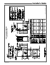
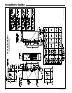
2. Do all clearances between the furnace and enclo-
sure equal or exceed the minimums stated in Clear-
ance Table on the Outline Drawings.
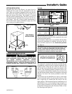
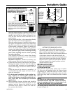
3. Is there sufficient space for servicing the furnace
and other equipment? A minimum of 24 inches
front accessibility to the furnace must be provided.
Any access door or panel must permit removal of
the largest component.
4. Are there at least 3 inches of clearance between the
furnace combustion air openings in the front panel
and any closed panel or door provided?
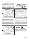
5. Are the ventilation and combustion air openings
large enough and will they remain unobstructed? If
outside air is used, are the openings set above the
highest snow accumulation level? (See the Air for
Combustion and Ventilation section.)
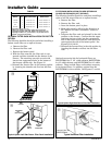
6. Allow sufficient height in supply plenum above the
furnace to provide for cooling coil installation, if the
cooling coil is not installed at the time of this furnace
installation.
7. A furnace shall be installed so electrical components
are protected from water.
8. If the furnace is installed in a residential garage,
it must be installed so that the burners, and the ig-
nition source are located not less than 18 inches
above the floor and the furnace must be located or
protected to avoid physical damage from vehicles.
GENERAL INSTALLATION INSTRUCTIONS
The manufacturer assumes no responsibility for equip-
ment installed in violation of any code or regulation.
It is recommended that Manual J of the Air Condition-
ing Contractors Association (ACCA) or A.R.I. 230 be fol-
lowed in estimating heating requirements. When esti-
mating heating requirements for installation at Alti-
tudes above 2000 ft., remember the gas input must be
reduced (See GAS INPUT ADJUSTMENT).
Material in this shipment has been inspected at
the factory and released to the transportation
agency without known damage. Inspect exterior
of carton for evidence of rough handling in ship-
ment. Unpack carefully after moving equipment
to approximate location. If damage to contents is
found, report the damage immediately to the de-
livering agency.
Codes and local utility requirements governing the
installation of gas fired equipment, wiring, plumbing,
and flue connections must be adhered to. In the ab-
sence of local codes, the installation must conform with
latest edition of the National Fuel Gas Code ANSI
Z223.1 • National Installation Code, CAN/CGA B149.1.
The latest code may be obtained from the American Gas
Association Laboratories, 400 N. Capitol St. NW,
Washington D.C. 20001.
1-800-699-9277 or www.aga.org
These furnaces have been classified as Fan Assisted
Combustion system CATEGORY I furnaces as required
by ANSI Z21.47 “latest edition” and CAN/CGA 2.3.
Therefore they do not require any special provisions for
venting other than what is indicated in these instruc-
tions. (Category I defined on page 14).
These furnaces may be twinned. They shall have
common returns with equal pressure drops or
ducts with equivalent lengths and sizes. See Field
Wiring Diagrams for Twinning on page 17 for
proper hookup.