


12 18-CD21D1-5
Installer’s Guide
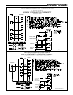
UPFLOW FURNACE RETURN AIR FILTERS
CABINET
WIDTH
QTY*
CABINET
BOTTOM FILTER
CABINET
SIDE FILTER
14-1/2" 1 14" X 25" X 1" 17-1/2" X 25" X 1"
17-1/2" 1 17" X 25" X 1" 17-1/2" X 25" X 1"
21" 1 20" X 25" X 1" 17-1/2" X 25" X 1"
24-1/2" 1 24" X 25" X 1" 17-1/2" X 25" X 1"
*First letter may be "A" or "T"
**NOTE: For upflow 5 ton airflow models where the airflow
requirement exceeds 1800 CFM - Modles will require return air
openings and filters on: (1) both sides, or (2) one side and the
bottom, or (3) just on the bottom
TABLE 4
OPTIONAL FILTER RACK INSTALLATION FOR BOTTOM
RETURN
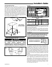
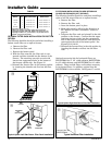
The following checklist should be used when installing a
bottom return filter on an upflow furnace:
a. Remove the filter.
b. Remove the filter rack.
c. Remove the bottom panel.
d. With the filter removed, the filter rack is com-
pressed and then inserted into the bottom of the
furnace. The retaining screw/pin on each side
inserts into engagement holes at the bottom of
the furnace cabinet side. See Figure 18.
e. Reinstall the furnace filter in the bottom position
by inserting the chamfer end first into the filter
rack.
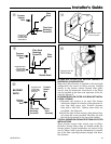
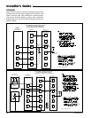
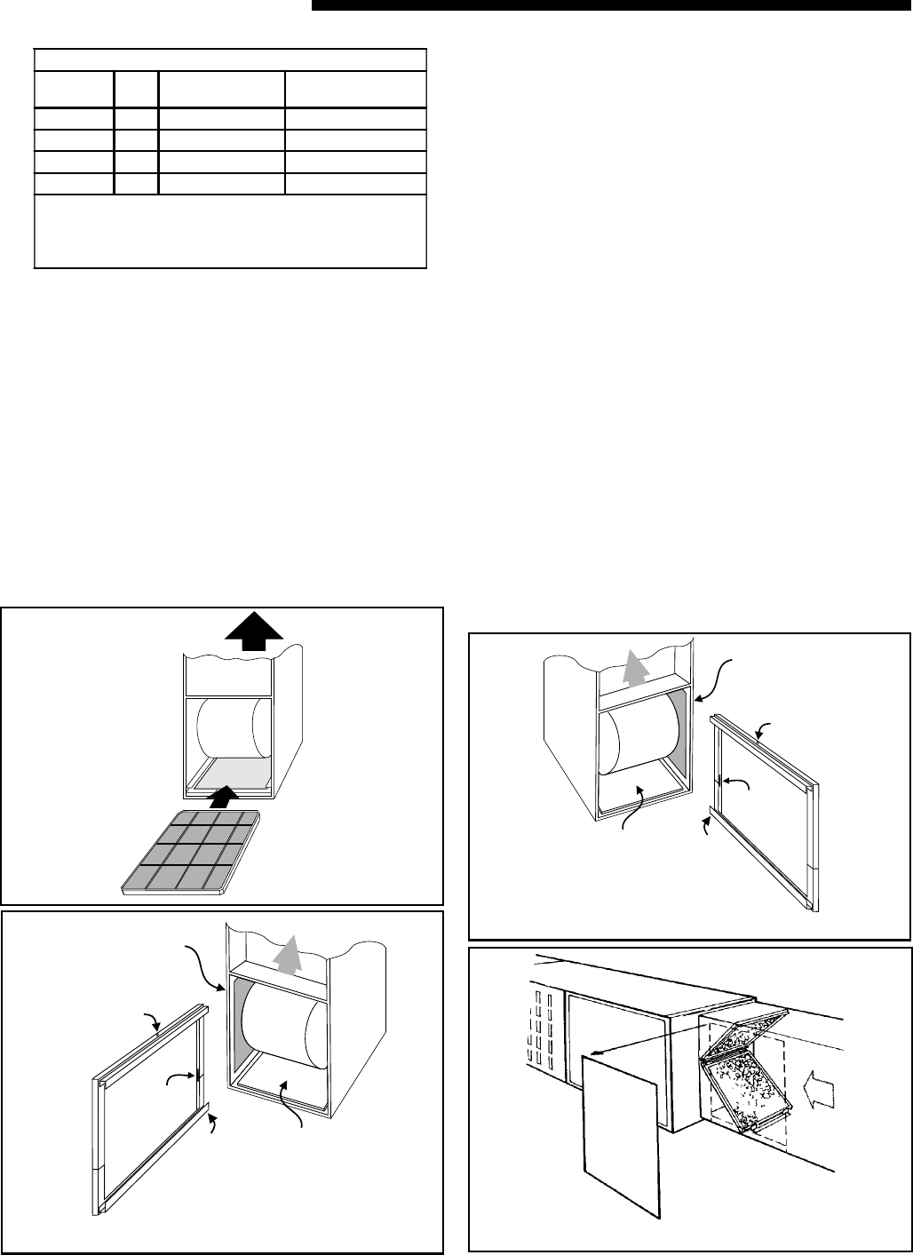
FILTER RACK INSTALLATION FOR SIDE RETURN AIR
ON UPFLOW FURNACES (LEFT OR RIGHT)
The following checklist should be used when installing a
right or left side return filter on an upflow furnace:
a. Remove the filter.
b. Remove the filter rack.
c. Leave the bottom panel in place.
d. Make side cutout by following the directions in
the “Return Air Duct Connections” section on
page 10.
e. Compress the filter rack and reinstall in the side
position on the furnace. Confirm that the upper
retaining pin/screw locks into the engagement
hole in the blower deck and the lower pin/screw
rests against the side of the bottom panel. See
Figures 15-16, 19-20.
f. Reinstall the furnace filter in the side position by
inserting the chamfer end first into the filter
rack.
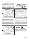
Airflow
r
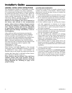
Typical Upflow Left Side Return Filter Rack Installation
RETAINING
PIN
(Both Sides)
SPRINGS
SIDE
CUTOUT
FILTER
RACK
RAILS
BOTTOM
PANEL
INSTALLED
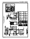
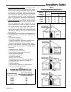
Airflow
Airflow
t
RETAINING
PIN
(Both Sides)
SPRINGS
SIDE
CUTOUT
FILTER
RACK
RAILS
BOTTOM
PANEL
INSTALLED
Airflow
Airflow
y
Typical Upflow Right Side Return Filter Rack Installation
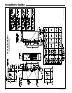
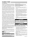
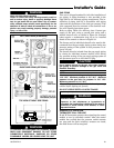
Airflow
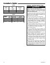
Typical Horizontal Filter Installation
u
Optional conversion kits for horizontal filters are
BAYFLTR203 for 17 1/2" width cabinets, BAYFLTR204
for 21" width cabinets, and BAYFLTR205 for 24" width
cabinets. These include filters and brackets necessary
for horizontal filters. In addition, optional door kit
BAYFLTR206 is also available. See Figures 17 and 22.
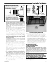
Optional door kit
BAYFLTR206