


20 18-CD21D1-5
Installer’s Guide
When the thermostat is satisfied, R and W thermostat
contacts open, the gas valve will close, the flames will
extinguish, and the induced draft blower will be de-en-
ergized. The indoor blower motor will continue to run
for the fan off period (fixed at 100 seconds), then will be
de-energized by the control module.
▲
WARNING
!
FIRE OR EXPLOSION HAZARD
Failure to follow the safety warnings exactly could re-
sult in serious injury, death or property damage. Never
test for gas leaks with an open flame. Use a commer-
cially available soap solution made specifically for the
detection of leaks to check all connections. A fire or ex-
plosion may result causing property damage, personal
injury, or loss of life.
START-UP AND ADJUSTMENT
PRELIMINARY INSPECTIONS
With gas and electrical power “OFF”
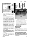
1. Duct connections are properly sealed
2. Filters are in place
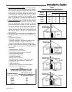
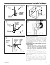
3. Venting is properly assembled
4. Blower door is in place
Turn knob on main gas valve within the unit to the
“OFF” position. Turn the external gas valve to “ON”.
Purge the air from the gas lines. After purging, check
all gas connections for leaks with a soapy solution – DO
NOT CHECK WITH AN OPEN FLAME. Allow 5 min-
utes for any gas that might have escaped to dissipate.
LP Gas, being heavier than air, may require forced ven-
tilation. Turn the knob on the gas valve in the unit to
the “ON” position.
COMBUSTION AND INPUT CHECK
1. Make sure all gas appliances are off except the fur-
nace.
2. Clock the gas meter with the furnace operating (de-
termine the dial rating of the meter) for one revolu-
tion.
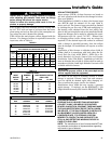
3. Match the “Sec” column in the gas flow (in cfh)
Table 12 with the time clocked.
4. Read the “Flow” column opposite the number of sec-
onds clocked.
5. Use the following factors
if necessary:
For 1 Cu. Ft. Dial Gas Flow CFH =
Chart Flow Reading ÷ 2
For 1/2 Cu. Ft. Dial Gas Flow CFH =
Chart Flow Reading ÷ 4
For 5 Cu. Ft. Dial Gas Flow CFH =
10X Chart Flow Reading ÷ 4
6. Multiply the final figure by the heating value of the
gas obtained from the utility company and compare
to the nameplate rating. This must not exceed the
nameplate rating.
7.Changes can be made by adjusting the manifold
pressure or changing orifices (orifice change may
not always be required). To adjust the manifold
pressure:
a.Turn off all electrical power to the system.
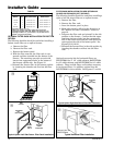
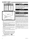
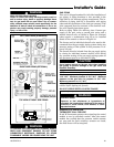
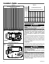
b.Attach a manifold pressure gauge to the outlet pres-
sure tap marked "OUT PRESS TAP" on White-
Rodgers gas valve model 36F or boss marked "OUT
P" on White-Rodgers gas valve model 36G. (See Fig-
ure 26 for White-Rodgers gas valve model 36F and
Figure 25 for White-Rodgers gas valve model 36G).
For the gas valve model 36F, measurement re-
quires removal of the plug and installation of a
barbed fitting. Attach flexible tubing and a manom-
eter to the barbed fitting.
For the gas valve model 36G, do not remove the
pressure tap test screw. Using a 3/32" hex wrench,
loosen the pressure tap test screw one turn and in-
stall 5/16" flexible tubing and a manometer directly
onto the outlet pressure boss.
c. Turn on system power and energize valve.
d.Remove the regulator adjustment screw cap on the
gas valve for manifold pressure adjustment.
e.Turn the adjustment nut clockwise to increase the
gas flow rate, and counterclockwise to decrease the
gas flow rate using a 3/32" hex wench.
f. The final manifold pressure setting shall be 3.5"
W.C. with an input of no more than nameplate rat-
ing and no less than 93% of the nameplate rating,
unless the unit is derated for high altitude.
g.Replace the regulator adjustment screw cap and
tighten securely.
h.Turn off all electrical power to the system.
i. Remove the manometer and flexible tubing. Re-
move the barbed fitting and replace the plug or
tighten the pressure test screw.
j. Turn on electrical power to the system and energize
valve.
k. Using a leak detection solution or soap suds, check
for leaks at plug or pressure boss screw.
As the induced draft blower comes up to speed, the
pressure switch contacts will close and the ignitor warm
up period will begin. The ignitor will heat for approx. 20
seconds, then the gas valve is energized to permit gas
flow to the burners. The flame sensor confirms that ig-
nition has been achieved within the 6 second ignition
trial period.
After the flame sensor confirms that ignition has been
achieved, the delay fan ON period (fixed at 45 seconds)
begins timing. After the delay of 45 seconds, the indoor
blower motor will be energized and will continue to run
during the heating cycle.