


7SSP-PRC002-EN
Selection
Procedure
Cooling Capacity
Step 1 — Calculate the building’s total
and sensible cooling loads at design
conditions. Use the Trane calculation
form or any other standard accepted
method.
Step 2 — Size the equipment using Table
PD-1. Match the cooling loads at design
conditions.
Example: The following are the building
cooling requirements
a
Electrical Characteristics: 380-415/50/3
b
Summer Design Conditions: Entering
Evaporator Coil: 80 DB/67 WB
(27 DB/19 WB°C)
Outdoor Ambient: 95°F (35° C)
c
Total Cooling Load: 75 MBh (22kW)
d
Sensible Cooling Load: 53 MBh
(15.5 kW)
e
Airflow: 2500 cfm (4247 m
3
/h)
External Static Pressure: 0.77 in. wg
(193 Pa)
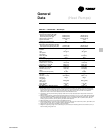
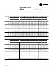
Table PD-1 shows that a TWA075A
matched with a TWE075A has a gross
cooling capacity of 82.4 MBh (24.1 kW)
and 59.5 MBh (17.4 kW) sensible capacity
at 95 DB (35°C) ambient and 2500 cfm
(4247 m
3
/h) and 80 DB/67 WB (27 DB/19
WB) air entering the evaporator.
To find the net cooling capacities, fan
motor heat must be subtracted.
Determine the total unit static pressure:
External Static 0.77 in (193 Pa)
Standard Filter 0.10 in (25 Pa)
Supplementary Electric Heat
0.23 in (57 Pa)
Total Static Pressure 1.10 in (275 Pa)
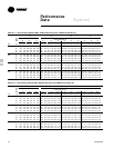
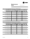
Note: The Evaporator Fan Performance
Table has included the effect of a 1 in.
(250 Pa) filter already. Therefore, the
actual Total Static Pressure is 1.10 - 0.10 =
1.00 in. (275 - 25 = 250 Pa).
With 2500 cfm (4247 m
3
/h) and 1.00
inches (250 Pa), Table 26-1 shows a 1.07
bhp (0.8 kW).
Note: The formula below the table can be
used to calculate Fan Motor Heat,
Constant x Motor Power =
Fan Motor Heat
3.5 x bhp = MBh
3.5 x 1.07 = 3.75 MBh
1.375 x (kW) = kW
1.375 x 0.8 = 1.1 kW
Net Total Cooling Capacity
= 79.6 MBh – 3.75 = 75.85 MBh
= 23.3 kW - 1.1 = 22.2 kW
Net Sensible Cooling Capacity
= 57.1 MBh – 3.75 = 53.35 MBh
= 16.7 MBh - 1.1 = 15.6 kW
Heating Capacity
Step 1 — Calculate the building heating
load using the Trane calculation form or
any other standard accepted method.
Step 2 — Size the equipment using Table
PD-9 to match the heating loads at
design conditions. The following are
building heating requirements:
a
Total Heating Load: 110 MBh (32.2 kW)
b
Outdoor Ambient (Winter): 17°F
(-8.3°C) DB
c
Indoor Return Temperature: 70°F
(21.1°C) DB
d
Airflow: 2500 cfm (4247 m
3
/h)
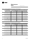
Table PD-9 indicates the mechanical
heating portion of the heat pump will
provide 37.5 MBh (11.0 kW) for the winter
design conditions.
Step 3 — Because 37.5 MBh (11.0 kW) is
less than the building’s required heating
capacity, a supplementary heater must
be selected. 110 - 37.5 = 72.5 MBh (32.2 -
11.0 = 21.2 kW) minimum heater capacity.
From Table PD-25, the 24.22 kW heater
has a capacity of 82,670 Btu. From Table
34-1, the 24.22 kW heater at 400V
indicates the heater model number is
BAYHTRL435A. This heater will be
adequate to cover the residual heat
capacity needed for the application.
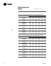
Air Delivery Selection
External static pressure drop through the
air distribution system has been
calculated to be 0.77 inches (192.5 Pa) of
water gauge. From Table PD-24 static
pressure drop through the electric heater
is 0.12 inches (30 Pa) of water (0.77 + 0.12
= .89 in.) (192.5 + 30 = 222.5 Pa). Enter
Table PD-15 for TWE090A4 at 2500 cfm
(4247 m
3
/h) and .90 in. (225 Pa) static
pressure. The standard motor at 790 rpm
will give the desired airflow.