


TRG-TRC016-EN 83
period four
Chiller-Plant Control
notes
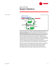
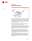
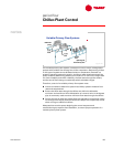
Today’s chiller controls can very accurately control the chiller’s leaving-water
temperatures over a wide range of loads. This is especially true of centrifugal
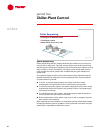
and helical-rotary chillers. This fact allows constant-flow chilled-water systems,
similar to the system shown in Figure 91, to use the system supply- and return-
water temperatures to determine system load.
By sensing a rise in the temperature of the water leaving the chiller plant,
the control system can determine when the operating chillers can no longer
maintain the desired temperature. Often, the supply-water temperature is
allowed to drift a predetermined amount before an additional chiller is turned
on, to ensure that there is enough load to keep an additional chiller operating.
Deciding when it is appropriate to turn a chiller off is more complex. The control
system may monitor the system ∆T, that is, return-water temperature minus
supply-water temperature. This information, along with the capacities of the
operating chillers, allows the control system to determine when a chiller can be
turned off. To help stabilize system operation, the control system should use
logic to prevent load transients from causing unwarranted chiller cycling.
In constant-flow systems that are suffering from “low ∆T syndrome” (airside
systems that return water to the plant at lower temperatures than desired),
some of the load terminals may starve for flow before the capacity of the
operating chiller is exceeded. To preserve system efficiency, this situation is
best dealt with by solving the airside problem. Typical causes of low ∆T
syndrome include: a poorly-balanced flow system, dirty filters or coils,
poorly performing air-handler controls, incorrect coil control valves, or
undersized air handlers.
load indicators
Temperature
supply
supply
-
-
water
water
temperature
temperature
return
return
-
-
water
water
temperature
temperature
chiller
chiller
-
-
plant
plant
controller
controller
Figure 91