


64 TRG-TRC016-EN
notes
period three
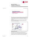
System Variations
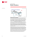
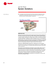
Variable-Primary-Flow Systems
One of the reasons that many chilled-water systems are installed using the
primary-secondary configuration is that, in the past, chillers could not respond
well to varying water flow through the evaporator. Therefore, the production
loop was designed for a constant flow through the chillers, and the distribution
loop was designed for variable flow to take advantage of the pump energy
savings. The system was hydraulically decoupled to meet these two goals.
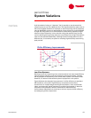
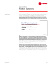
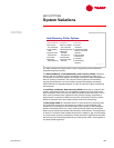
Alternatively, in a variable-primary-flow (VPF) system, the flow of water
varies throughout the entire system—through the evaporator of each operating
chiller as well as through the cooling coils. The VPF system differs from the
primary-secondary system in that it no longer hydraulically decouples the two
loops. The variable-flow pumps move the water through the entire system.
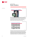
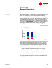
The primary benefit of this system is the elimination of the separate distribution
pump(s) and the associated electrical and piping connections. There is also a
small reduction in operating cost because there is seldom excess water flowing
through the bypass pipe.
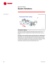
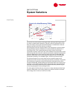
VPF systems, however, require chillers that can operate properly when the
water flow through the evaporator varies. Many of today’s chillers can tolerate
variable water flow through the evaporator, within limits. These limits include
minimum and maximum flow rates and a limitation on how quickly the flow can
vary. Exceeding these operating limits may cause control instability or even
catastrophic failure. The VPF system therefore requires a method of monitoring
the flow rate through each chiller and a control system to ensure that the flow
through the evaporator stays within the limits for the specific chiller. Do not
attempt to use a VPF system with chillers that have older, analog electric,
or pneumatic controls that cannot handle variable evaporator flow.
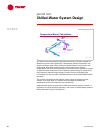
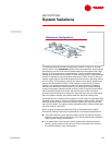
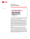
Variable-Primary-Flow Systems
b
y
p
a
s
s
b
y
p
a
s
s
two
two
-
-
way
way
valve
valve
variable
variable
-
-
flow
flow
pumps
pumps
control
control
valve
valve
check
check
valves
valves
optional bypass
optional bypass
with three
with three
-
-
way valve
way valve
Figure 72