


42 TRG-TRC016-EN
notes
period two
Chilled-Water System Design
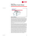
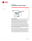
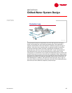
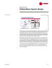
The bypass pipe is common to both production and distribution loops.
The purpose of the bypass pipe is to hydraulically decouple the production
(primary) and distribution (secondary) pumps. Because water can flow freely
between the supply and return pipes for both loops, a change in flow in one
loop does not affect the flow in the other loop.
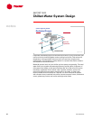
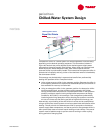
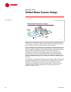
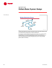
The actual extent of hydraulic decoupling depends on the pressure drop due to
the bypass pipe. Total decoupling is accomplished only if the bypass pipe is free
from restrictions and large enough to produce no pressure loss at all flow rates.
Because zero pressure loss is not practical, some insignificant pump coupling
will exist. Bypass pipes are typically sized so that the water velocity in the pipe
will be 10 to 15 ft/s [3 to 4.5 m/s], based on the water flowing through the
bypass pipe at the design flow rate of the largest chiller in the system.
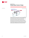
Additionally,
to further minimize pressure drop, the bypass pipe is usually relatively short in
length. To prevent random mixing of the supply and return water streams,
however, the minimum length of the bypass pipe is typically 5 to 10 pipe
diameters.
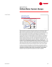
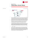
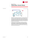
When designing the bypass pipe, an important issue to keep in mind is that the
bypass pipe must be kept free of unnecessary restrictions. For example, a check
valve must not be installed in the pipe. Restrictions cause hydraulic coupling
that can result in unacceptable chiller flow variations or unstable, and
potentially harmful, system pressure variations due to the resulting series-
pumping effects. If a manual isolation valve is required for service, it should
be large enough to ensure that it does not add significant pressure drop to the
bypass pipe.
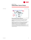
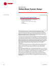
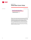
Primary-Secondary System Rules
▲ The bypass pipe should be free of restrictions
◆ Sized for minimal pressure drop
◆ Avoid random mixing of supply- and return-water
streams
◆ No check valve
Figure 48