


14 PKG-SVX17A-EN
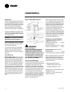
Note:
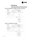
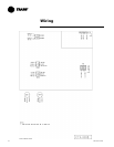
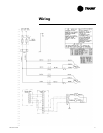
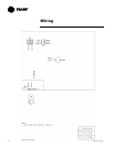
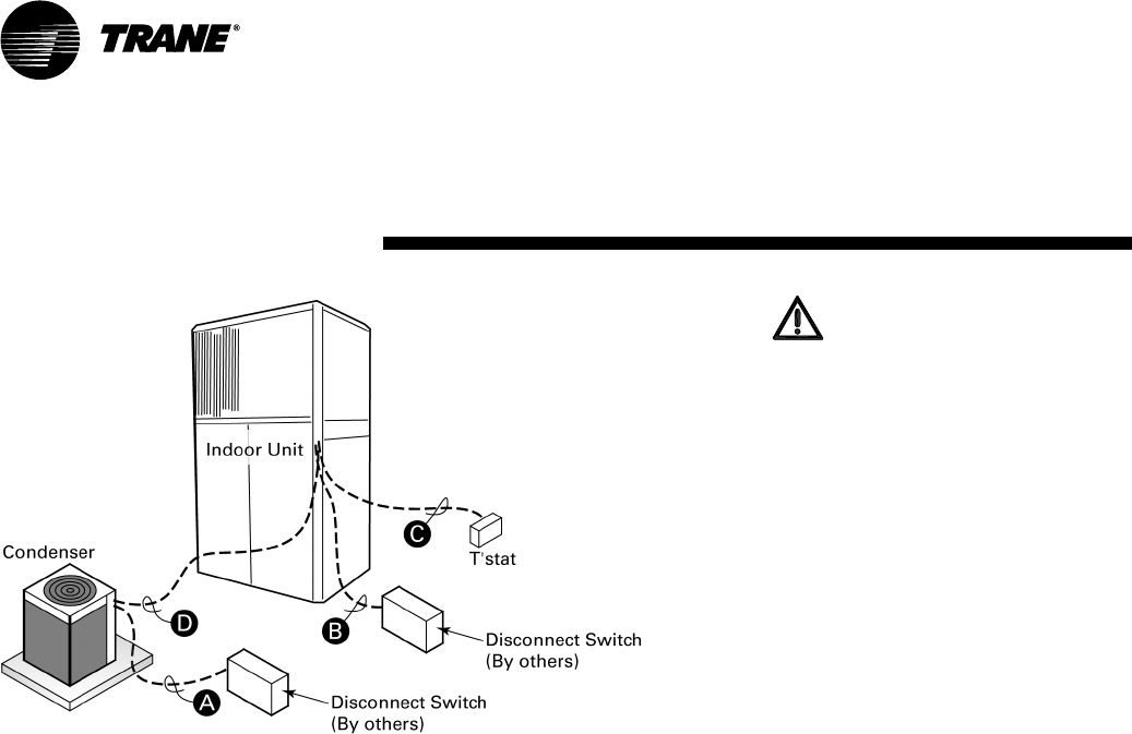
1. Wiring shown with dashed lines is to
be furnished and installed by the cus
-
tomer. All customer supplied wiring
must be copper only and must con-
form to NEC and local electrical codes.
Codes may require line of sight be-
tween disconnect switch and unit.
CTA090A/S(C,I)RH030
CTA090A/S(C,I)RH050
CTA120A/S(C,I)RH075
CTA120B/S(C,I)RH100
Field Wiring:
A — 2 power wires. Line voltage for
single phase
B — 3 power wires. Line voltage for
3 phase; 2 wires for single phase
C — Cooling only thermostat: 3 wires,
24 volts.
— Digital thermostat: add 1 addi-
tional wire, 24 volts.
D — 2 control wires, 24 volts.
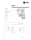
CTA180B/S(C,I)RH120
CTA180B/S(C,I)RH150
Field Wiring:
A — 2 power wires. Line voltage for
single phase
B — 3 power wires. Line voltage for
3 phase
C — Cooling only thermostat: 4 wires,
24 volts.
D — 3 control wires, 24 volts.
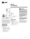
WARNING:
Hazardous Voltage w/Capacitors!
Disconnect all electrical power,
including remote disconnects and
discharge all motor start/run ca
-
pacitors before servicing. Follow
proper lockout/tagout procedures
to ensure the power cannot be in
-
advertently energized. Verify with
an appropriate voltmeter that all
capacitors have discharged. Fail
-
ure to diconnect power and dis-
charge capacitors before
servicing could result in death or
serious injury.
Note: For additional information
regarding the safe discharge of
capacitors, see PROD-SVB06A-EN
or PROD-SVB06A-FR.
Determine proper wire sizes and unit
protective fusing requirements by
referring to the unit nameplate. Field
wiring diagrams for accessories
are shipped with the accessory.
Wiring
Low Voltage
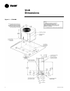
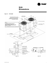
Figure 8: Typical Field Wiring