


10 PKG-SVX17A-EN
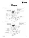
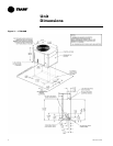
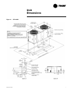
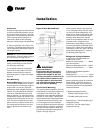
Clearances
Provide enough space around the unit
to allow unrestricted access to all ser-
vice points. Refer to Figure 1 through
Figure 4 for unit dimensions and mini-
mum required service and free air
clearances. Observe the following
points to insure proper unit operation.
A. Do not install the unit under a low
overhang. Condenser discharge must
not be restricted. See Notes in Figure
1 through Figure 4.
NOTICE: Do not obstruct condenser
discharge air. This can result in warm
air recirculation through the coil.
B. Do not locate the unit in a position
where runoff water can fall into the
fan discharge openings.
C. Condenser intake air is supplied
from three or four sides of the unit.
Adhere to the minimum required
clearances given in Figure 1 through
Figure 4.
Unit Mounting
Rooftop Mounting: If the unit will be
roof mounted, determine for certain
that the structure is strong enough to
support the unit and any required
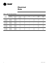
accessories. Unit weights are given in
Table 2. The unit should be elevated
on a level, field fabricated four-inch
steel or wood 4" x 4" mounting frame.
Complete the frame and secure it into
position before lifting the unit to the
roof. The mounting frame must sup
-
port a minimum of three of the unit’s
four sides and should span roof sup-
ports to distribute the load on the
roof.
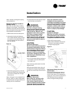
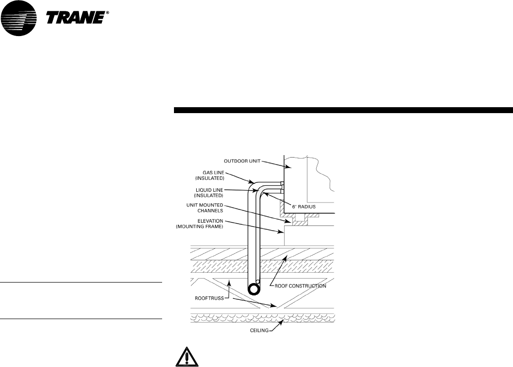
Figure 5 Roof Mounted Unit
WARNING
Structural Failure!
Ensure that the roof structure
supports are strong enough to
support the weight of the unit
and any accessories. Failure to do
this could result in death or seri
-
ous injury due to structural fail-
ure and could seriously damage
the unit and the building.
Ground Level Mounting
“For ground level installation, the unit
base should be adequately supported
and hold the unit near level. The
installation must meet the guidelines
set forth in local codes.” The support
should extend two inches beyond the
unit base channels at all points. The
unit and support must be isolated
from any adjacent structure to prevent
possible noise or vibration problems.
Any ground level location must com
-
ply with required clearances given in
Figure 1 through Figure 4.
Holes must be made in the structure
to run refrigerant lines. For the major
-
ity of ground-level installations, the
holes can be made in the header that
rests on top of the foundation. Alter
-
natively, these holes may also be
made in the foundation itself. On roof-
mounted units, refrigerant lines
should enter the building as close to
the unit as possible; preferably within
three to four inches of the refrigerant
connection on the unit, plus a six-inch
(long radius) 90 degree "L" entering
the building (See Figure 5).
Refrigerant Piping Guidelines
A. Maximum recommended line
lengths: (per circuit)
Maximum linear length..............200 Ft.
(w/o accumulator)
Maximum discharge line lift......200 Ft.
Maximum liquid line lift..............60 Ft.
B. Maximum allowable pressure
drops (R-410A):
Discharge line...............................10 psi
Liquid line (without subcooler)...50 psi
Route refrigerant piping for minimum
linear length, minimum number of
bends and fittings (no reducers) and
minimum amount of line exposed to
outdoor ambients.
C. Recommended line sizes:
CTA090, 120A (single circuit)
CTA120B, 180B (dual circuit)
Discharge line - 7/8 inch sealed type L
refrigerant tubing.
Liquid line - 1/2 inch sealed type L
refrigerant tubing.
Installation