


PKG-SVX17A-EN 13
Table 3: CTA Refrigerant Charge
Model
Refrigerant Charge
(R-410A)*
CTA090A
w/SCRH030
18.1 lbs
CTA090A
w/SCRH050
19.9 lbs
CTA120A
w/SCRH075
20.8 lbs
CTA120B
w/SCRH100
11.9 lbs
(Ckt. #1 & #2)
CTA180B
w/SCRH120
16.8 lbs. (Ckt. #1)
16.0 lbs. (Ckt. #2)
CTA180B
w/SCRH150
17.5 lbs. (Ckt. #1)
16.9 lbs. (Ckt. #2)
* Sufficient operating charge for listed unit
and 33 feet of nominally sized refrigerant
piping.
Table 4: Additional Refrigerant
Tubing Sizes Additional
Tubing
Length
Additional
Refrig.
Discharge Liquid
7/8" 1/2" 15 ft. 1.3 lbs
7/8" 1/2" 25 ft. 2.2 lbs
7/8" 1/2" 32 ft. 2.8 lbs
7/8" 1/2" 40 ft. 3.5 lbs
Note: Amounts shown are based on 0.087
lbs of refrigerant per foot of 7/8" and 1/2"
lines.
Note: For tubing over 40 feet, calculate
the additional refrigerant needed,
based on notes above.
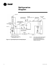
Gaseous Charging
This procedure is accomplished with
the unit operating. Electrical connec
-
tions must be complete. Do not pro-
ceed until the system is ready to
operate.
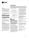
Procedure
1. Connect R-410A drum with gauge
manifold to the gauge ports (pres
-
sure taps) on the compressor dis-
charge and suction lines (Figure 7).
Note: On the CTA units, the service
access panel must be installed when
the unit is running and being charged.
WARNING:
Hazardous Energy Sources!
Use extreme caution while servic-
ing the unit when the control box
access panel is removed and
power is applied to the unit. Fail
-
ure to observe all safety precau-
tions could result in death or
serious injury.
2. Turn on power to the unit. Allow the
system to run for five to ten minutes
to stabilize operating conditions.
3. Measure airflow across the indoor
coil. Compare the measurements
with the fan performance data in the
Data/Submittal.
4. Check suction line superheat and
condenser sub-cooling to ensure
the unit is operating properly.
5. Disconnect all power to the unit.
WARNING:
Hazardous Voltage
w/Capacitors!
Disconnect all electrical power,
including remote disconnects and
discharge all motor start/run ca
-
pacitors before servicing. Follow
proper lockout/tagout procedures
to ensure the power cannot be in
-
advertently energized. Verify with
an appropriate voltmeter that all
capacitors have discharged. Fail
-
ure to diconnect power and dis-
charge capacitors before
servicing could result in death or
serious injury.
Note: For additional information
regarding the safe discharge of
capacitors, see PROD-SVB06A-EN
or PROD-SVB06A-FR.
6. Remove the charging system from
the unit and replace all access pan
-
els.
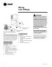
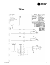
Electrical Wiring
CTA field wiring consists of providing
power supply to the unit, installing the
system indoor thermostat and provid
-
ing low voltage system interconnect-
ing wiring. Access to electrical
connection locations is shown in Fig
-
ures 1 through 4.
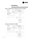
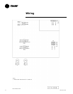
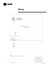
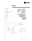
Unit Power Supply
The installer must provide line voltage
circuit(s) to the unit main power termi
-
nals as shown by the unit wiring dia-
grams in Figures 9 and 10 on page 15.
Power supply must include a discon
-
nect switch in a location convenient to
the unit. Ground the unit according to
local codes and provide flexible con-
duit if codes require and/or if vibration
transmission may cause noise prob
-
lems.
CAUTION:
Use Copper Conductors Only!
Unit terminals are not designed to
accept other types of conductors.
Failure to use copper conductors
may result in equipment damage.
CAUTION:
All wiring must comply with appli-
cable local and national NEC
codes. Type and location of dis
-
connect switches must comply
with all applicable codes.
WARNING:
Ground Wire!
All field-installed wiring must be
completed by qualified personnel.
All field-installed wiring must
comply with NEC and applicable
local codes. Failure to follow this
instruction could result in death
or serious injuries.
WARNING:
Grounding Required!
Follow proper local and state elec-
trical code on requirements for
grounding. Failure to follow code
could result in death or serious in
-
jury
Installation