


WSHP-SVN08B-EN 9
General Installation Checks
The checklist below is a summary of
the steps required to successfully in-
stall a unit. This checklist is intended to
acquaint the installing personnel with
procedures required in the installation
process. It does not replace the de-
tailed instructions called out in the ap-
plicable sections of this manual.
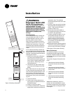
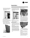
1 Remove packaging and inspect the
unit. Check the unit for shipping
damage and material shortage; file
a freight claim and notify appropri-
ate sales representation.
Note: The unit cabinet is packaged
in a wooden crate. A pry bar and/
or hammer will be needed for
packaging removal.
The chassis sits inside a cardboard
tray with an upper box for protec-
tion. Typically four chassis will be
shrink-wrapped to a single pallet.
2 Verify the correct model, options
and voltage from the unit name-
plate.
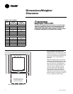
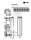
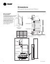
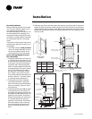
3 Verify the installation location of
the unit will provide the required
clearance for proper operation.
4 Remove refrigeration access panel
and inspect the unit. Be certain the
refrigerant tubing has clearance
from adjacent parts.
WARNING
Hazardous
Voltage!
Disconnect all electric power,
including remote disconnects and
discharge all motor start/run
capacitors before servicing.
Follow proper lockout/tagout
procedures to ensure the power
can not be inadvertently
energized. Failure to disconnect
power before servicing could
result in death or serious injury.
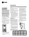
Main Electrical
5 Verify the power supply complies
with the unit nameplate specifica-
tions.
6 Inspect all control panel compo-
nents; tighten any loose connec-
tions.
7 Connect properly sized and pro-
tected power supply wiring to a
field-supplied/installed disconnect
switch and to the unit power block
(1TB1) in the unit’s cabinet control
box for equipment.
8 Install proper grounding wires to
an earth ground.
Note: All field-installed wiring must
comply with NEC and applicable local
codes.
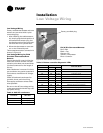
Low Voltage Wiring (AC & DC)
Requirements
9 Connect properly sized control wir-
ing to the proper termination
points between the field supplied
thermostat and the terminal plug
in the equipment’s junction box.
Installation
!