


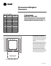
10 WSHP-SVN08B-EN
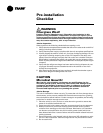
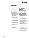
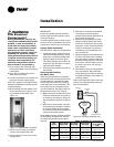
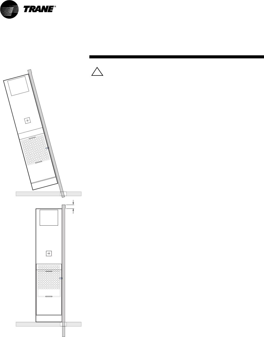
FLOOR
FLOOR
3" SWAGE
WARNING
Improper Unit Lift!
Test lift unit approximately 24
inches to verify proper center of
gravity lift point. To avoid
dropping of unit, reposition lifting
point if unit is not level. Failure to
properly lift unit could result in
death or serious injury or possible
equipment or property-only
damage.
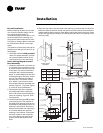
Unit Placement
If unit cabinet assembly includes fac-
tory provided risers, and "no" field
provided between-the-floor riser ex-
tensions, please move to Step 1.
Note: Risers are designed to accom-
modate a maximum of 1 1/2" to 3" ex-
pansion and contraction. If the total
calculated riser expansion exceeds 3",
expansion devices must be field pro-
vided.
If unit cabinet assembly includes fac-
tory provided risers and field provided
between-the-floor riser extensions are
required, install the extensions before
installing the cabinet.
1 Install drain valve, shut-off/balanc-
ing valves, flow indicators and
drain at the base of each supply and
return riser to enable system flush-
ing at start-up, balancing and ser-
vice/maintenance.
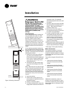
2 Lift cabinet into space while align-
ing it into the 3"swage of the riser
below.
Note: Take extra care as not to scrape
or dent risers during positioning. The
riser should fall approximately 2" into
the 3" swage. This will allow for the
variation in floor-to-floor dimensions,
and keep the riser joints from bottom-
ing out.
3 Level the cabinet.
4 Plumb risers in two planes to as-
sure proper unit operation and con-
densate drainage.
5 Anchor all units into place.
6 For field provided risers, center the
supply/return stubouts into the unit
expansion slots. The stubouts
should be perpendicular to the cab-
inet panel.
7 Verify all risers are vertical and that
they penetrate the swaged joint at
least 1". Riser should not be al-
lowed to bottom out.
8 Braze riser joints. Soft solder or
low-temperature alloys should not
be used in this application.
9 If risers are field provided, it is rec-
ommended that the risers be an-
chored to the building structure
with a minimum of one contact
point. For expansion and contrac-
tion reasons, do not fasten risers
rigidly to the building.
10 Seal access holes made through the
cabinet for piping with suitable ma-
terial to help eliminate air leakage.
11 See page 14 for system flushing.
Water Connection
For vibration isolation, it is recom-
mended that flexible steel braided
hoses be installed instead of hard pip-
ing between the vertical risers and the
unit chassis.
Trane offers 4-types of hose kit varia-
tions:
• Stainless steel braided flexible
hose with manual shut-off (ball)
valves
• Stainless steel braided flexible
hose with manual deluxe shut-off
(ball) valves
• Stainless steel braided flexible
hose with manual circuit-setter
valve
• Stainless steel braided flexible
hose with automatic balancing
valve
Additional accessories, such as a
strainer are recommended for use to
eliminate contaminants from entering
the co-axial water-to-refrigerant heat
exchangers.
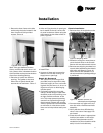
Installation
Figure 2: Stacking illustration
!