


20 WSHP-SVN08B-EN
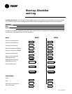
Initial Unit Start-up
Start-up with deluxe controls is included below:
Note: Start-up for the Tracer
TM
ZN510 controller may be found in WSHP-IOP-2.
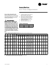
WARNING
Live Electrical Components!
During installation, testing, servicing and troubleshooting of this product, it may be necessary to work with
live electrical components. Have a qualified licensed electrician or other individual who has been properly
trained in handling live electrical components perform these tasks. Failure to follow all electrical safety pre-
cautions when exposed to live electrical components could result in death or serious injury.
1. Set the thermostat to the highest position.
2. Set the thermostat system switch to COOL with the fan control to AUTO. The compressor should NOT run.
3. Reduce the temperature control setting until the compressor, reversing valve, solenoid valve, and loop
pump are energized. Adjust water flow utilizing pressure/temperature plugs and comparing to tables con-
tained in specification sheet data. Water leaving the heat exchanger should be warmer than the entering
water temperature (approximately 9°F-12°F); blower operation should be smooth; compressor and blower
amps should be within data plate ratings; the suction line should be cool with no frost observed in the
refrigerant circuit.
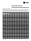
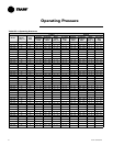
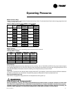
4. Check the cooling refrigerant pressures against values in Table OP1. (Page 21).
5. Turn the thermostat switch to the OFF position. Unit should stop running and the reversing valve should
de-energize.
6. Leave unit off for approximately FIVE minutes to allow for pressure equalization.
7. Turn the thermostat to the lowest setting.
8. Set the thermostat system switch to the HEAT position.
9. Adjust the temperature setting upward until the unit is energized. Warm air should blow from the register.
A water temperature decrease of approximately 5°F-9°F leaving the heat exchanger should be noted. The
blower and compressor operation should be smooth with no frost observed in the refrigeration circuit.
10. Check the heating refrigerant pressures against values in Table OP1. (Page 21)
11. Set the thermostat to maintain the desired space temperature.
12. Instruct the owner on system operation.
Sequence
of Operation
!