


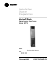

WSHP-SVN08B-EN 5
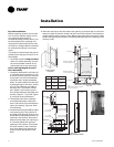
Unit Nameplate
The unit nameplate is located at the
front of the unit. It includes the unit
model number, serial number, electri-
cal characteristics, refrigerant charge,
and other pertinent unit data.
Compressor Nameplate
The nameplate for the compressors
are located on the compressor shell.
Unit Description
Before shipment, each unit is leak test-
ed, dehydrated, charged with refriger-
ant and run tested for proper control
operation.
Water-to-Refrigerant Coils
The co-axial water-to-refrigerant heat
exchanger for the 3/4-ton through 3-
ton equipment is constructed of cop-
per or cupro-nickel (option) for the wa-
ter section and stainless steel for the
refrigeration section.
The heat exchanger is leak tested to
assure there is no cross leakage be-
tween the water and refrigerant gas.
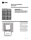
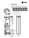
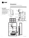
Water Connections
1/2" or 3/4" water connections are lo-
cated on the chassis’s upper section
and clearly labeled for water-in/out
hose to riser hook-up.
Blower/Motor
The blower and motor is located inside
the unit cabinet. The blower and motor
may be removed from the cabinet
through the chassis opening. After re-
moving the chassis, the blower as-
sembly is strapped into the unit
cabinet through a single metal, flexi-
ble bracket. We refer to this bracket as
a housing belly bracket. After detach-
ing one screw at the bottom/front edge
of the bracket, the housing and motor
are free to be lifted from the fan deck.
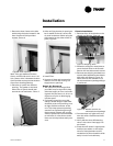
Sound Attenuation
Sound attenuation is applied as a stan-
dard feature in the product design. The
enhanced reduction package includes
a heavy gage base plate, and gasket/
insulation around the compressor en-
closure.
An optional deluxe sound reduction
package is also available. It includes a
heavy gage base plate, gasket and in-
sulation around the compressor enclo-
sure, and vibration isolation between
the chassis and cabinet. An additional
dampening treatment is applied
around the compressor enclosure to
achieve greater acoustical reductions.
Controls
The control system offered to control
the unit is a Basic 24 volt control for
the 3/4-ton through 2-ton retrofit
(WPRD) equipment. A 50 VA trans-
former is factory supplied on this unit
configuration. See wiring diagram on
chassis access panel for field wiring
connection to the 24 volt mechanical
thermostat.
Deluxe 24V Controls
(GET model)
Units containing the Deluxe 24V con-
trol design will incorporate a micro-
processor-based control board. The
Trane microprocessor board is factory
wired to a terminal strip to provide all
necessary terminals for field connec-
tion. The deluxe board is equipped
with a random start relay, anti-short
cycle timer, brown out protection,
compressor disable, unit safety con-
trol, diagnostics and a generic relay
(which may be available for field use).
See page 16 for diagnostic informa-
tion.
Power wiring is made at the contactor.
The wiring is fed through the left or
right conduit tube, and into the cabi-
net’s control box (contactor).
ZN510 Controls
(GET option)
Units incorporating the ZN510 control
option design will include a digital
LonTalk
TM
certified control board. The
control board will support such op-
tions as: random start delay, heating/
cooling status, occupied/unoccupied
mode and fan/filter status.
Power wiring is made at the contactor.
The wiring is fed through the left or
right conduit tube, and into the cabi-
net’s control box (contactor). See
manual WSHP-IOP-2 for diagnostic in-
formation.
Schrader Connections
Connections for the low and high side
of the refrigeration system are located
conveniently on the chassis’ top be-
neath a sheet metal plate.
General
Information