


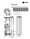

WSHP-SVN08B-EN 11
Field Installed Power Wiring
Power wiring to the equipment must
conform to National and Local Electric
Codes (NEC) by a professional electri-
cian.
WARNING
Live Electrical
Components!
During installation, testing, ser-
vicing and troubleshooting of this
product, it may be necessary to
work with live electrical compo-
nents. Have a qualified licensed
electrician or other individual
who has been properly trained in
handling live electrical compo-
nents perform these tasks. Failure
to follow all electrical safety pre-
cautions when exposed to live
electrical components could re-
sult in death or serious injury.
Verify that the power supply available
is compatible with the unit’s name-
plate. Use only copper conductors to
connect the power supply to the unit.
CAUTION
Use Copper
Conductors Only!
Unit terminals are not designed
to accept other types of conduc-
tors. Failure to use copper con-
ductors may result in equipment
damage.
Main Unit Power Wiring
A field supplied disconnect switch
must be installed at or near the unit in
accordance with the National Electric
Code (NEC latest edition).
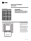
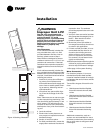
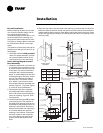
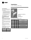
Location of the applicable electric ser-
vice entrance for HIGH (line voltage)
may be found in Figure 3.
1 Route power wire to the cabinet
control box through the factory in-
stalled conduit at the top of the unit
cabinetry.
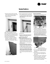
The high voltage connection is made
at the 1PB1 power block in the cabinet
control box. Refer to the customer
connection diagram that is shipped
with the unit for specific termination
points.
Provide proper grounding for the unit
in accordance with the local and na-
tional codes.
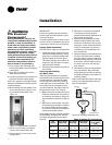
Control Power Transformer
The 24-volt control power transform-
ers are to be used only with the acces-
sories called out in this manual.
Transformers rated greater than 50 VA
are equipped with internal circuit
breakers. If a circuit breaker trips, turn
OFF all power to the unit before at-
tempting to reset it.
WARNING
Hazardous Voltage!
Disconnect all electric power, in-
cluding remote disconnects and
discharge motor start/run capaci-
tors before servicing. Follow prop-
er lockout/tagout procedures to
ensure the power can not be inad-
vertently energized. Failure to dis-
connect power before servicing
could result in death or serious in-
jury.
The transformer is located in the
chassis control box.
Installation
FACTORY CONDUIT
Figure 3: Power wire entrance
!
!