


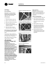
Installation
34 CAH-SVX01A-EN
• Thermal expansion valve. The
expansion valve is the throttling
device that meters the
refrigerant into the evaporator
coil. Metering too much
refrigerant floods the
compressor; metering too little
elevates the compressor
temperature. Choosing the
correct size and type of
expansion valve is critical to
assure it will correctly meter
refrigerant into the evaporator
coil throughout the entire
operating envelope of the
system. Correct refrigerant
distribution into the coil requires
an expansion valve for each
distributor.
The thermal expansion valve must
be selected for proper size and
capacity. The size of the expansion
valve should cover the full range of
loadings. Check that the valve will
successfully operate at the lightest
load condition. For improved
modulation, choose expansion
valves with balanced port
construction and external
equalization.
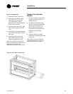
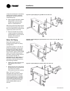
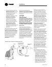
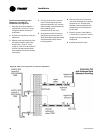
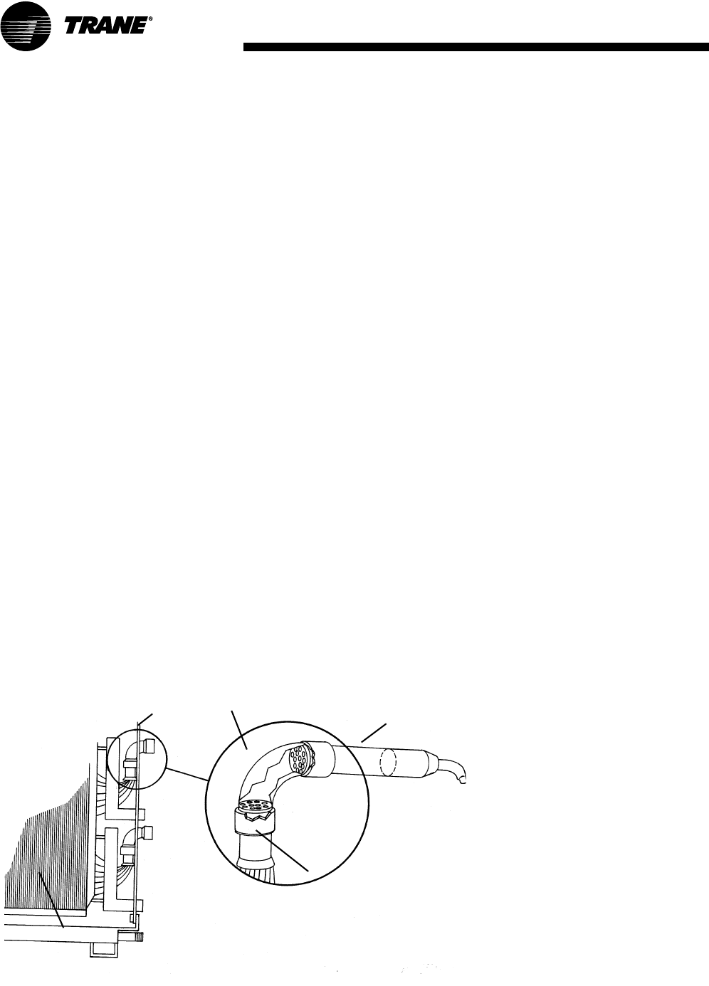
Figure 34. Type F refrigerant coil with packed elbow
Panel
Perforated plate
(packed elbow)
Cut here for
piping
Venturi type
distributor
Coil
Cut the process tube and cap
assembly from the liquid connection
as shown in Figure 34 and install the
expansion valve directly to the liquid
connections.
CAUTION
Valve Damage!
Disassemble the thermal expansion
valve before completing the brazing
connections. If necessary, wrap the
valve in a cool, wet cloth while
brazing. Failure to protect the valve
from high temperatures may result
in damage to internal components.
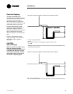
Suction Lines
Line sizing. Proper suction-line
sizing is required to guarantee the
oil returns to the compressor
throughout the system’s operating
envelope. At the same time, the line
must be sized so that the pressure
drop does not excessively affect
capacity or efficiency. To accomplish
both objectives, it may be necessary
to use two different line diameters:
one for the horizontal run and for
vertical drops, and another for the
vertical lifts.
Routing. To prevent residual or
condensed refrigerant from “free-
flowing” toward the compressor,
install the suction line so it slopes
slightly—that is, by 1/4-inch to 1-inch
per 10 feet of run [1 cm per 3 m]—
toward the evaporator. When the
application includes a suction riser,
oil must be forced to travel the
height of the riser. Riser traps and
double risers are unnecessary in the
suction line when the refrigerant coil
is used with Trane condensing units.
Avoid putting refrigerant lines
underground. Refrigerant
condensation or installation debris
inside the line, service access, and
abrasion/corrosion can quickly
impair reliability.
Insulation. Any heat that transfers
from the surrounding air to the
cooler suction lines increases the
load on the condenser (reducing the
system’s air-conditioning capacity)
and promotes condensate formation
(adversely affecting indoor air
quality). After operating the system
and testing all fittings and joints to
verify the system is leak-free,
insulate the suction lines all the way
to inner side panel to prevent heat
gain and unwanted condensation.
Components. Installing the suction
line requires field installation of
these components: a filter, access
port, and a Frostat™ control when
the refrigerant coil is used with
Trane condensing units. Position
them as close to the compressor as
possible.
Note: Placement of the Frostat
control is illustrated in Figure 33.
• Filter. The suction filter prevents
contaminants, introduced during
installation, from entering the
compressor. For this reason, the
suction filter should be the
replaceable-core type, and a
clean core should be installed
after the system is cleaned up.
• Access port. The access port is
used to determine suction
pressure. This port is usually a
Schraeder valve with a core.