


Installation
CAH-SVX01A-EN 25
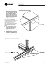
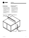
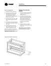
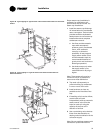
3 Check that the bushing on the
isolator stud is centered in the
isolator. Adjust to center by
moving the stud in the fan base
hole.
4 This procedure will raise the
equipment load until the
isolators are all off the shims
(shipping tie-down blocks)
approximately 1/32-inch (the
thickness of a credit card), and
the internal gap is approximately
equal to the external gap.
Note: Do not adjust isolators once
the fan base is off of the shipping tie
down blocks.
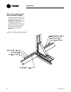
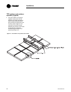
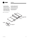
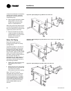
5 Continue adjusting other
isolators in sequence and repeat
the same adjustment. Continue
until all isolators are adjusted.
6 Replace the jam nut on each
isolator adjusting bolt, tighten
the nut, and remove the shipping
tie down block.
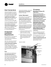
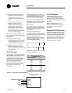
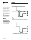
Traq™ Dampers
Traq dampers are low-leak dampers
that modulate and measure airflow.
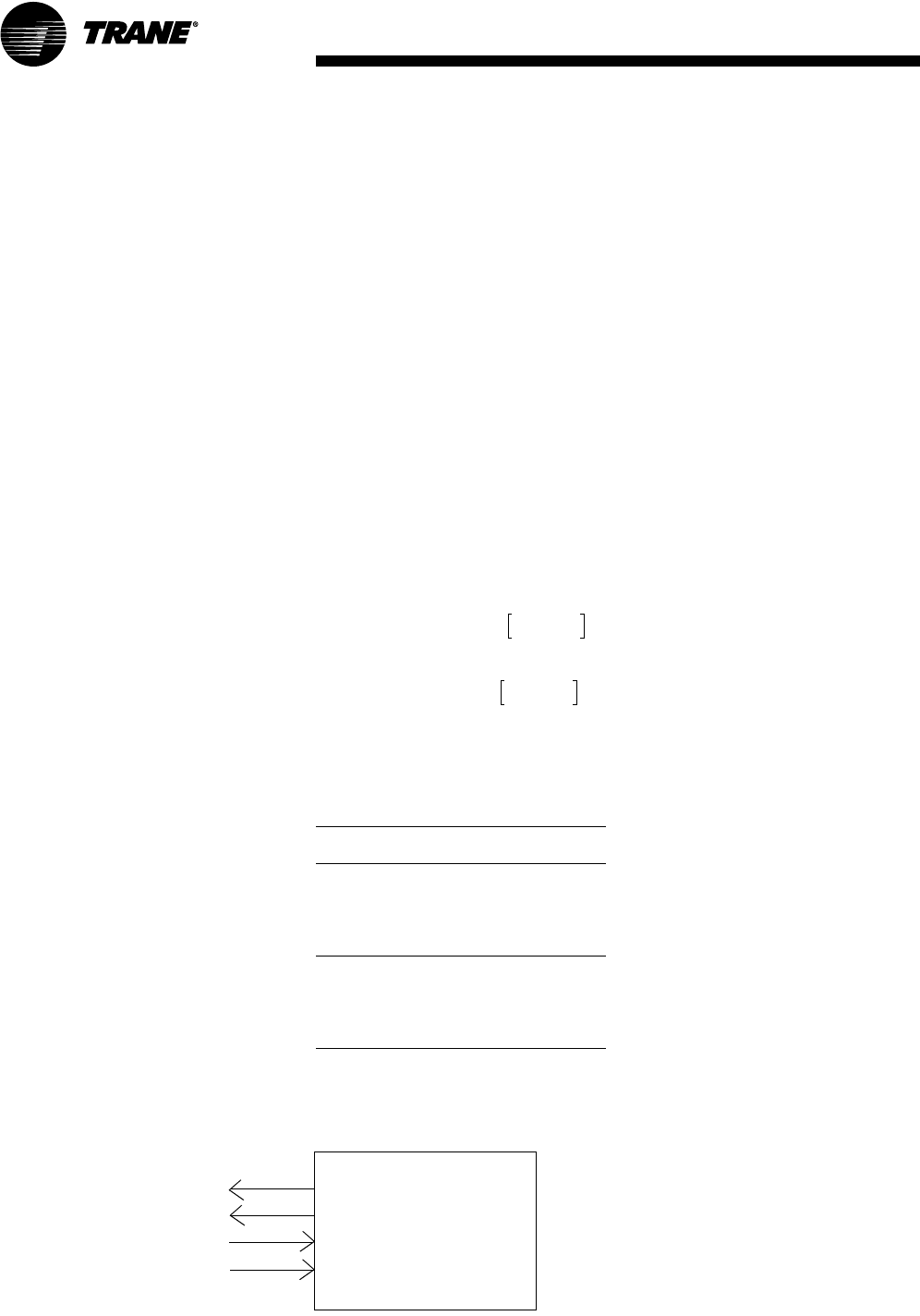
Each Traq damper module is
supplied with a factory-mounted
ventilation control module (VCM) on
the interior of the mixing box
module. The VCM has an input
terminal for power and an output
terminal for air velocity (see
Figure 20).
Figure 20. Traq damper terminal connections
Ventilation Control
Velocity (2–10 Vdc)
GND
24 Vac
GND
1TB1–3
1TB1–4
1TB1–5
1TB1–6
Module
The actuators, factory-mounted or
field-supplied, are separately wired
and controlled by a direct-digital
controller or other building logic.
VCM (Transducer) Calibration. The
VCM has an auto-zero function that
recalibrates the transducer once
every minute.
Input Power Signal. The only input
signal the VCM needs is the 24 Vac
power connected to terminals 1TB1-
5 and 1TB1-6.
Output Velocity Signal. The
2to10VDC linear output signal from
the VCM represents air velocity. This
voltage can be converted to
represent airflow (cfm or L/s) using
the formula below, Table 1 and data
in your submittal package.
Airflow = k (cfm @ 10V)
OR
Airflow = k (L/s @ 10V)
Altitude can be adjusted for by using
the following factors:
Table 1. Altitude adjustment factors
Sea level = 1.0
Elevation (feet) k
1000 0.982
2000 0.964
3000 0.949
4000 0.930
5000 0.914
6000 0.897
7000 0.876
8000 0.860
9000 0.846
10,000 0.825
volts 2–()
8
------------------------------
volts 2–()
8
------------------------------
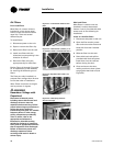
Control Dampers
If the damper actuators are not
factory mounted install damper
actuators and connecting linkage.
Check damper operation and linkage
alignment.
Damper blades should be non-
binding. Adjust damper frame as
necessary to ensure free blade
movement.
Magnahelic Air Filter Gage
Check zero adjustment of the gage.
Turn both vent valves to the “Vent”
position and adjust the gage pointer
to zero by means of the external
adjustment screw in the face of the
gage. After zeroing, turn the vent
valves to the “Line” position.