


Installation
CAH-SVX01A-EN 33
Refrigerant Coil Piping
Note: Refer to the “Protecting the
Environment” section on page 3 for
information on handling
refrigerants.
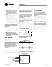
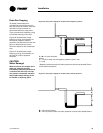
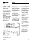
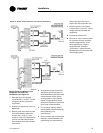
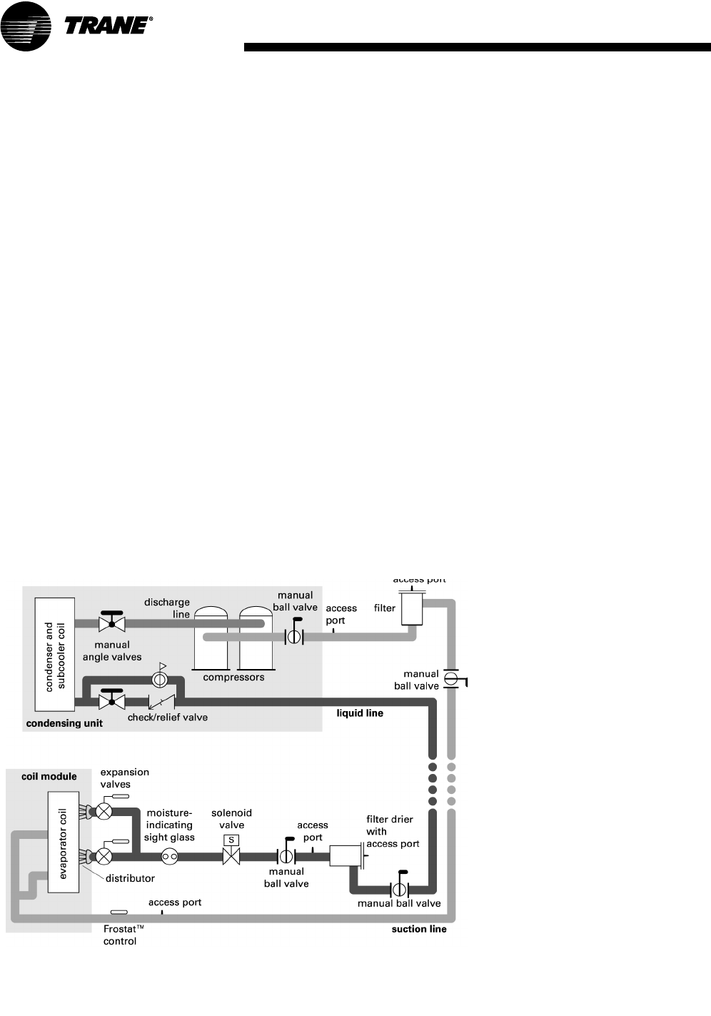
Use Figure 33 to determine the
proper, relative sequence of the
components in the refrigerant lines
that connect the condensing unit to
an evaporator coil. Refer to the
“Examples of Field-Installed
Evaporator Piping” section on
page 35 for more detailed
schematics of evaporator piping.
Liquid Lines
Line Sizing. Properly sizing the liquid
line is critical to a successful split-
system application. The selected
tube diameter must provide at least
5°F [2.7°C] of subcooling at the
expansion valve throughout the
operating envelope. Increasing the
size of the liquid line will not
increase the available subcooling.
Figure 33. Example of placement for split-system components
Kit with Kit Kit
Kit with sensor 13790452010 SEN-01212
Kit with switch - X13100429010 THT 02442
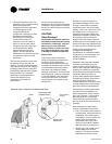
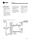
Routing. Install the liquid line with a
slight slope in the direction of flow
so that it can be routed with the
suction line. Minimize tube bends
and reducers because these items
tend to increase pressure drop and
to reduce subcooling at the
expansion valve. Liquid line
receivers, other than those that are
factory-installed, are not
recommended.
Insulation. The liquid line is
generally warmer than the
surrounding air, so it does not
require insulation. In fact, heat loss
from the liquid line improves system
capacity because it provides
additional subcooling.
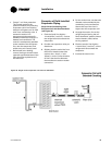
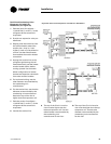
Components. Liquid-line refrigerant
components necessary for a
successful job include a filter drier,
access port, solenoid valve,
moisture-indicating sight glass,
expansion valve(s), and ball shutoff
valves. Figure 33 illustrates the
proper sequence for positioning
them in the liquid line. Position the
components as close to the
evaporator as possible.
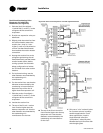
• Filter drier. There is no substitute
for cleanliness.during system
installation. The filter drier
prevents residual contaminants,
introduced during installation,
from entering the expansion
valve and solenoid valve.
• Access port. The access port
allows the unit to be charged
with liquid refrigerant and is
used to determine subcooling.
This port is usually a Schraeder
valve with a core.
• Solenoid valve. In split systems,
solenoid valves isolate the
refrigerant from the evaporator
during off cycles; under certain
conditions, they may also trim
the amount of active evaporator
as compressors unload.
Generally, the “trim” solenoid
valve is unnecessary for variable-
air-volume comfort-cooling
applications, and is only required
for constant-volume applications
when dehumidification is a
concern.
• Moisture-indicating sight glass.
Be sure to install one moisture-
indicating sight glass in the main
liquid line. The only value of the
sight glass is its moisture
indication ability. Use actual
measurements of temperature
and pressure—not the sight
glass—to determine subcooling
and whether the system is
properly charged. The moisture
indicator/sight glass must be
sized to match the size of the
liquid line at the thermal
expansion valve.