


Installation
CAH-SVX01A-EN 31
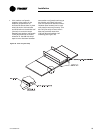
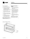
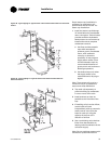
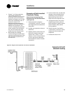
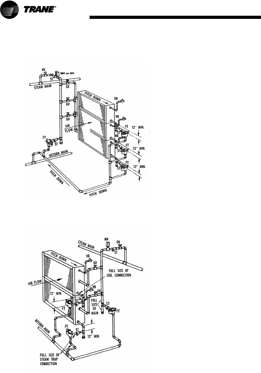
Figure 28. Typical piping for Type N steam coils and horizontal tubes for horizontal
airflow
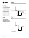
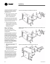
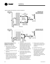
Figure 29. Typical piping for Type NS steam coils and horizontal tubes for
horizontal airflow
Proper steam trap installation is
necessary for satisfactory coil
performance and service life. For
steam trap installation:
1 Install the steam trap discharge
12 inches below the condensate
return connection. Twelve inches
provides sufficient hydrostatic
head pressure to overcome trap
losses and ensures complete
condensate removal.
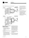
a Use float and thermostatic
traps with atmospheric
pressure gravity condensate
return, with automatic
controls, or where the
possibility of low-pressure
supply steam exists. (Float
and thermostatic traps are
recommended because of
gravity drain and continuous
discharge operation.)
b Use bucket traps only when
the supply steam is not
modulated and is 25 psig or
higher.
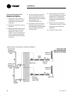
Note: Trane steam coils require a
minimum of 2 psi of pressure to
assure even heat distribution.
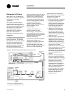
2 Trap each coil separately to
prevent holding up condensate
in one or more of the coils.
3 Install strainers as close as
possible to the inlet side of the
trap.
4 If installing coils in series airflow,
control each coil bank
independently with an automatic
steam-control valve. Size the
traps for each coil using the
capacity of the first coil in
direction of airflow.
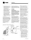
5 Use a modulating valve that has
linear flow characteristics to
obtain gradual modulation of the
coil steam supply.
Note: Do not modulate systems with
overhead or pressurized returns