


– 64 –
No. Part name
T
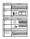
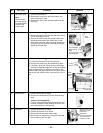
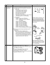
Control board
assembly
RemarksProcedure
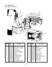
1) Disconnect lead wires and connectors connected
from the control board assembly to other parts.
1. Lead wires
• Connection with terminal block :
3 wires (Black, White, Orange)
• Connection with compressor :
Remove the connector (3P).
• Connection with reactor :
Remove the relay connectors from P07, 08
(2P, White) and P12, 13 (2P, Yellow).
2. Connectors
CN300 : Outdoor fan (3P, White)
CN301 : Outdoor fan position detection
(5P, White)
CN701 : 4 valve (3P, Yellow)
CN600 : TE sensor (2P, White)
CN601 : TD sensor (3P, White)
CN603 : TS sensor (3P, White)
CN602 : TO sensor (2P, White)
CN500 : Case thermo. (2P, White)
CN703 : Pulse modulating valve (6P, White)
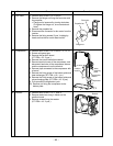
2) Remove the control board assembly from P.C.
board base.
1. Main control board assembly side
• Remove two claws of P.C. board base, and
remove upward the heat sink with hands.
• Remove three screws fixing the heat sink
and main control board assembly side, and
replace the board with a new one.
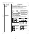
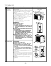
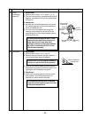
Reactor
U
Rear cabinet 1) Perform work of item 1 of
Q
, and
R
S
.
2) Remove fixed screws fixing to the bottom plate.
(ST1TØ4 x 10l 3 pcs.)
3) Remove fixed screws fixing to the heat
exchanger. (ST1TØ4 x 10l 2 pcs.)
4) Remove fixed screw fixing to the valve mounting
plate. (ST1TØ4 x 10l 1 pc.)
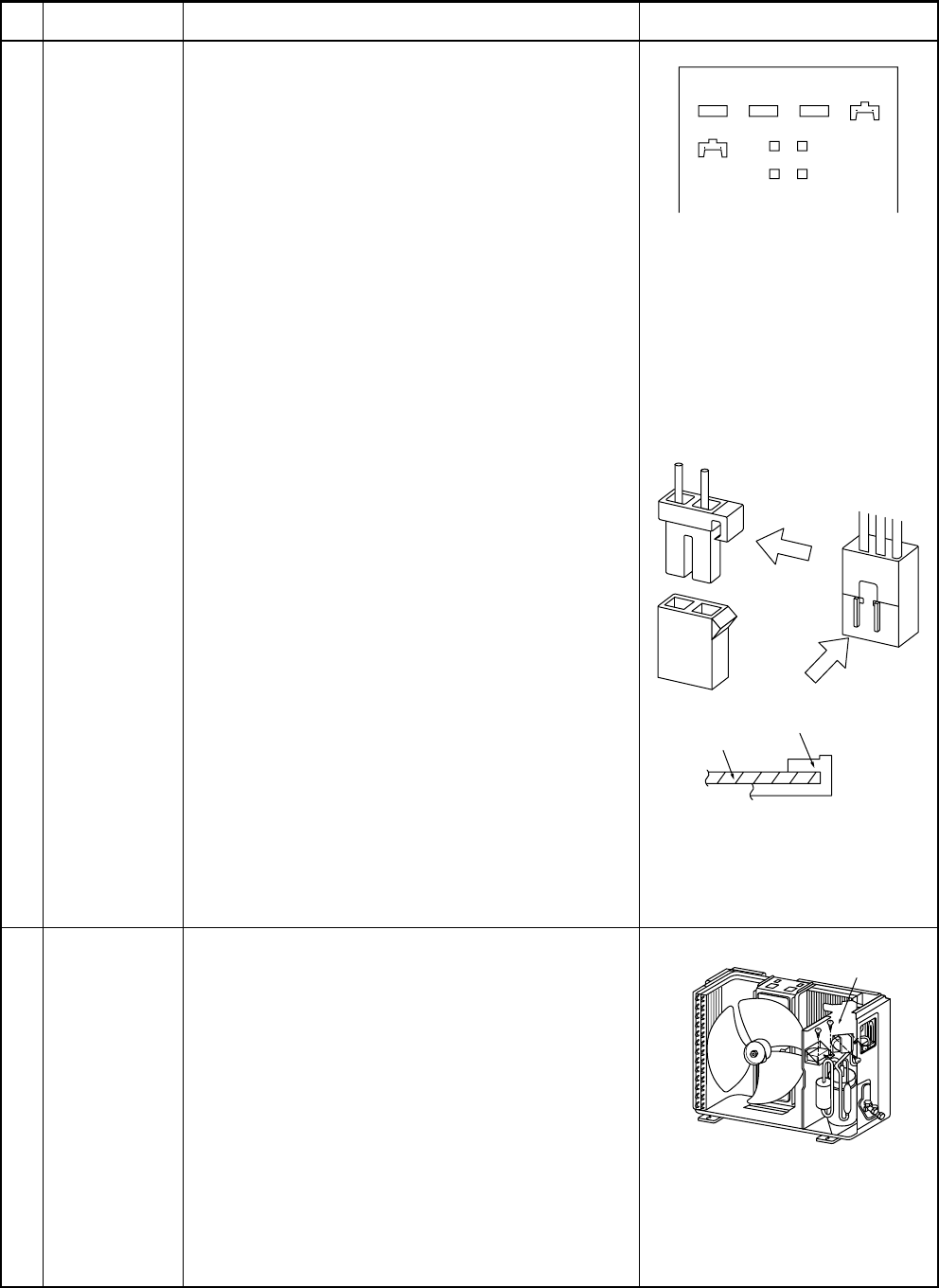
CN300, CN301 and CN701, etc.
at the control board assembly
side are connectors with locks.
Therefore, remove the connector
while pushing the part indicated
by an arrow.
When mounting a new board,
check that the board is correctly
set in the groove of base holder
of P.C. board base.
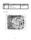
CN701CN500CN703CN301
P.C. board base
P.C. board
CN300
CN602
CN600
CN601
CN603