


– 69 –
FILE NO. SVM-03008
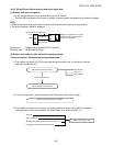
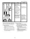
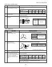
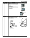
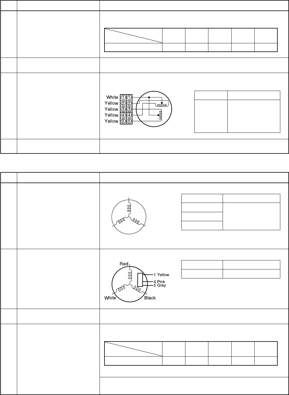
1 Room temp. (TA) sensor
Heat exchanger (TC) sensor
2 Remote control
3 Louver motor
MP24GA
4 Indoor fan motor
Disconnect the connector and measure the resistance value with tester.
(Normal temp.)
To item of How to judge whether remote control is good or bad of the Judgment
of trouble by symptom.
Measure the resistance value of each winding coil by using the tester.
(Under normal temp. 25°C)
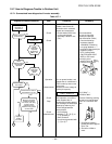
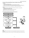
Since judgment of DC motor is difficult on the single motor, refer to 10-5-1. (3)
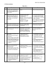
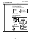
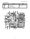
10-8-3. Indoor unit (Other parts)
No. Part name Checking procedure
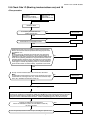
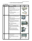
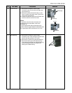
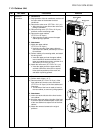
10-8-4. Outdoor unit
1 Compressor
(Model : DA91A1F-45F)
2 Outdoor fan motor
(Model : ICF-140-43-1)
3 Compressor thermo. Bimetal type
(Model : US-622KXTMQO-SS)
4 Outdoor temperature sensor
(TO), discharge temperature
sensor (TD), suction temperature
sensor (TS), outdoor heat
exchanger temperature sensor
(TE)
Temperature
10°C 20°C 25°C 30°C 40°C
Sensor
TA, TC (kΩ) 20.7 12.6 10.0 7.9 4.5
No. Part name Checking procedure
White Black
Red
Position Resistance value
1 to 2
1 to 3
380±40Ω
1 to 4
1 to 5
Measure the resistance value of each winding by using the tester.
Measure the resistance value of winding by using the tester.
For details, refer to Section 10-9.
Check conduction by using the tester.
Disconnect the connector, and measure resistance value with the tester.
(Normal temperature)
TGa : Heat pump model only.
TO, TS, TE : Refer to the TA, TC characteristic table in Indoor
(Refer to Table 10-8-3, No.1).
Position Resistance value
Yellow - Pink 5 to 20kΩ
Under 20°C
Position Resistance value
Red - White
White - Black 0.51 to 0.57Ω
Black - Red
Temperature
10°C 20°C 30°C 40°C 50°C
Sensor
TA, TC (kΩ) 105 64 41 27 18