


– 39 –
FILE NO. SVM-03008
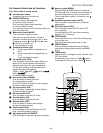
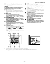
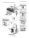
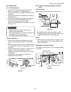
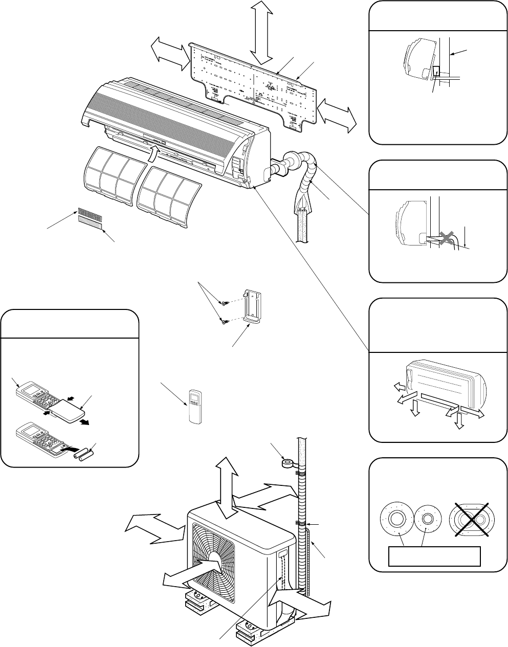
9-1-1. Installation Diagram of Indoor and Outdoor Units
Shield
pipe
A
ir
f
ilt
e
r
H
oo
k
Hook
(Attach to the front panel)
65 mm or more
1 Installation
plate
1
7
0
m
m
o
r
m
o
r
e
1
7
0
m
m
o
r m
o
r
e
For the rear left and left
piping
Insert the cushion between
the indoor unit and wall, and
lift the indoor unit for better
operation.
Wall
Insulate the refrigerant
pipes separately with
insulation, not together.
6 mm thick heat resisting
polyethylene foam
50 mm or more
from wall
Vinyl tape Apply
after carrying out
a drainage test
Extension
drain hose
(Option:
RB–821SW)
200 mm or more
600 mm or more
100 m
m
or m
ore
from
w
all
Saddle
Do not allow the drain hose
to get slack.
Make sure to run the drain
hose sloped downward.
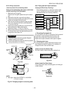
Cut the piping
hole sloped
slightly
Left
Rear
left
Right
Rear right
Bottom
right
Bottom left
The auxiliary piping can be
connected the left, rear left,
rear right, right, bottom right
or bottom left.
250 m
m
or m
ore
from
w
all
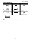
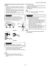
6 Purifying filter
5 Zeolite filter
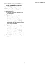
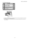
Before installing the
wireless remote control
• With the remote control cover
open, load the batteries supplied
correctly, observing their polarity.
2 Wireless remote control
3 Batteries
Cover
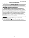
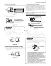
2 Wireless remote control
8 Flat head wood screw
4 Remote control holder
As show in the figure, hang
power cord and connecting
cable downward, and take out it
along piping connection port.
Fig. 9-1-1