


– 52 –
FILE NO. SVM-03008
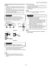
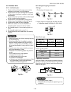
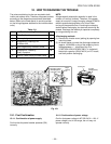
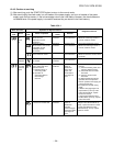
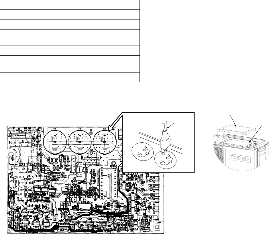
Inverter cover
P. C. board
(Soldered surface)
Discharging position
(Discharging period
10 seconds or more)
Plug of
soldering
iron
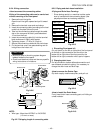
10. HOW TO DIAGNOSE THE TROUBLE
The pulse modulating circuits are mounted to both
indoor and outdoor units. Therefore, diagnose troubles
according to the diagnosis procedure as described
below. (Refer to the check points in servicing written
on the wiring diagrams attached to the indoor/outdoor
units.)
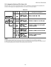
Table 10-1
No. Troubleshooting Procedure Page
1 First Confirmation 52
2 Primary Judgment 53
3 Judgment by Flashing LED 54
of Indoor Unit
4 Self-Diagnosis by Remote Control 55
5 Judgment of Trouble by 58
Every Symptom
6 How to Check Simply the Main Parts 66
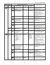
Fig. 10-1
NOTE:
A large-capacity electrolytic capacitor is used in the
outdoor unit control (inverter). Therefore, if the power
supply is turned off, charge (charging voltage DC280V)
remains and discharging takes a lot of time. After
turning off the power source, if touching the charging
section before discharging, an electrical shock may be
caused. Discharge the electrolytic capacitor completely
by using soldering iron, etc.
<Discharging method>
(1) Remove the inverter cover (plating) by opening four
mounting claws.
(2) As shown below, connect the discharge resistance
(approx. 100Ω40W) or plug of the soldering iron to
voltage between + – terminals of the C14
(“CAUTION HIGH VOLTAGE 380 V” is indicated.)
electrolytic capacitor (500µF/400 V) on P.C. board,
and then perform discharging.
10-1. First Confirmation
10-1-1. Confirmation of power supply
Confirm that the power breaker operates (ON)
normally.
10-1-2. Confirmation of power voltage
Confirm that power voltage is AC 220-240 V ± 10%. If
power voltage is not in this range, the unit may not
operate normally.