FILE NO. SVM-10019
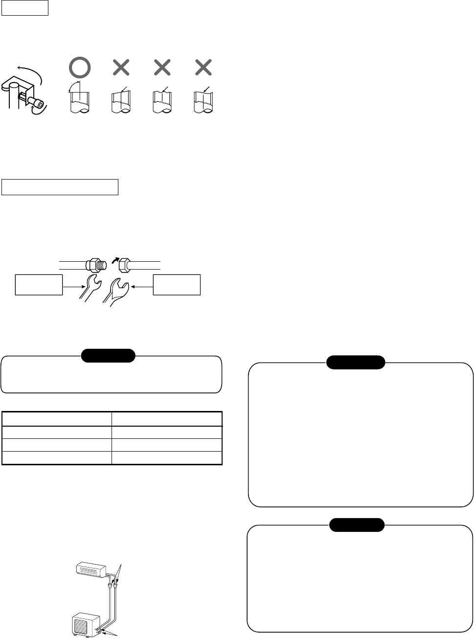
Do not apply excess torque. Otherwise, the nut
may crack depending on the conditions.
Outer dia. of copper pipe
Tightening torque
Ø1/4 in. (Ø6.35 mm) 10 to 13 lbf.ft (14 to 18 N·m)
Ø3/8 in. (Ø9.52 mm) 24 to 31 lbf.ft (33 to 42 N·m)
Ø1/2 in. (Ø12.70 mm) 37 to 46 lbf.ft (50 to 62 N·m)
Half union Flare nut
Externally
threaded side
Internally
threaded side
Use a wrench to secure. Use a torque wrench to tighten.
CAUTION
10-4-2. Refrigerant Piping Connection
Flaring
1. Make sure you have enough pipe to reach indoor unit.
90°
Obliquity Roughness WarpWarp
2. Cut the pipe with a pipe cutter.
3. Insert a flare nut into the pipe and flare the pipe.
Tightening connection
Align the centers of the connecting pipes and tighten
the flare nut as far as possible with your fingers.
Then tighten the nut with a two wrenches as show
below.
Fig. 10-4-2
Fig. 10-4-3
• Tightening torque for connection of flare pipe
The pressure of R410A is higher than R22.
(Approx. 1.6 times.) Therefore securely tighten the
flare pipes which connect the outdoor unit and the
indoor unit with the specified tightening torque
using a torque wrench.
Flare at
indoor unit side
Flare at
outdoor unit side
10-4-2. Wiring Connection
NOTE
All wiring and connections must comply with NEC,
CEC, local codes.
• Connect all wires to the correct terminal on the
wiring terminal blocks.
• Make sure that all connectors are secure.
• Size connectors per the ratings listed in the
system requirement section.
• System interconnections should be minimum
AWG14.
1. MOUNT THE OUTDOOR UNIT POWER
DISCONNECT.
2. ROW POWER WIRING FROM MAIN BOX TO
DISCONNECT PER NEC AND LOCAL CODES.
3. Remove the valve cover and the cord clamp from
the outdoor unit.
4. Fix conduit connector to conduit plate by lock nut
and secure it tightly. Connect the power supply and
connecting cables to the terminal block as shown
in figure and secure it tightly with screws.
5. You should not have extra cables.
6. Secure the power cord and the connceting cable
with the cord clamp.
7. Attach the electric parts cover and the valve cover
on the outdoor unit.
8. RUN PIPING AND INTERCONNECTING CABLE
TO THE INDOOR UNIT.
10-4-3. Electrical Work
ELECTRICAL SHOCK HAZARD
Failure to follow this warning could result in personal
injury or death.
The unit cabinet must have an uninterrupted or
unbroken ground to minimize personal injury if an
electrical fault should occur. The ground may
consist of electrical wire or metal conduit when
installed in accordance with existing electrical
codes.
Before performing service or maintenance, be sure
main power switch is turned OFF.
WARNING
UNIT DAMAGE HAZARD
Failure to follow this caution may result in equip-
ment damage or improper operation.
Unit failure as a result, or operation on improper
line voltage or excessive phase imbalance
constitutes abuse and may cause damage to
electrical components. Such operation could void
any applicable warranty.
CAUTION
– 61 –


