


82
INSTALLATION MANUAL
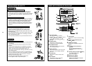
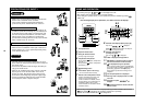
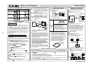
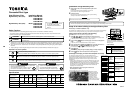
Accessory parts
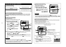
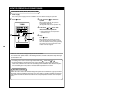
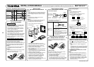
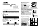
1. Inserting a minus screwdriver, etc. into the
groove at the lower side of the remote controller
body, force open the rear case to remove it.
2. Using the attached M4 screws (2 pcs.), fix the
rear case of the remote controller.
Before installation, press to open the screw hole
with a screwdriver, etc.
Fix it with the spacer, but not so strongly. If the
remote controller does not fit closely to the wall,
adjust it by cutting off the spacer.
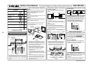
3. Connect the remote controller cable (2 cores) to
the cable from the remote controller body.
Connect the remote controller cable without
miswiring upon confirmation of the terminal
numbers of the indoor unit. (If applyied
AC 220/230/240V, may damage the unit.)
4. Install the remote controller body to hooks on the
rear case and putting into the hooks.
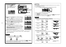
• Non polarity, 2 core cable is used.
• Use 0.5mm² to 2 mm² cable.
Cable from
remote controller body
Remote controller cable
Wire joint
Attached wire
joint
(White, 2 pcs.)
1) Peel the sheath of cable to be connected
by approx. 14mm.
2) Twist two cables and pressure-connect
them using a wire joint.
3) When an exclusive pressure-connecting
tool is not used or soldering connection
is used, apply insulation process with
an insulation tape.
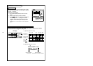
• Basic cabling diagram
NOTE :
Connect cables without miswiring.
(Miswiring breaks the unit.)
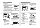
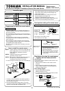
• In a case to operate an indoor unit from the
remote controllers at two positions
• How to install
For 2 remote controller control, install the remote
controllers in the following procedure.
1. Set one of the set multiple remote controllers to
the master remote controller.
(At shipment from factory)
2. For other remote controllers, turn the remote
controller address switch on the remote controller
P.C. board from OFF to ON. They function as sub
remote controllers under the above condition.
Remote controller test run setup
1. Push key after keeping [CHECK] button
pushed on the remote controller for 4 seconds or
more.
• During the test run, “TEST” is displayed on
LCD.
• The temperature cannot be controlled if [TEST]
is displayed. Do not use [TEST] in a case other
than a test run, otherwise an excessive load is
applied on the machine.
2. Use [TEST] in one of HEAT, COOL, and FAN
operation modes.
NOTE :
The outdoor unit does not operate for approx. 3
minutes after the power supply has been turned
on or the operation has stopped.
3. After the test run has finished, push [CHECK]
button again to check “TEST” on LCD has gone
off. (For this remote controller, a release function
of 60 minutes timer is provided to prevent
consecutive test runs.)
• In a case to operate a group control of multiple
indoor units from the remote controllers at two
positions
*
Master and sub remote controllers are operable
even if they are installed to any indoor unit.
Terminal block for
remote controller
cable in indoor unit
A
B
W : White
B : Black
W
B
Remote controller cable
(Procured locally)
Cable from
Remote controller
body
Connecting
section
Remote
controller
Q’ty
1
2
2
Part Name Part Name
Q’ty
2
2
1
1
Remote controller
Screw
M4 x 25
(200mm-cable
attached)
Wood screw
Spacer
Wire joint
Clamper
Installation Manual
Remote controller
body
Screws
M4 x 25 or
wood screws
(2 pcs.)
Rear case
Spacer
Wall
Earth
Remote controller
(Master)
Remote controller
(Sub)
BA
(Sold separately)
Terminal block for
remote controller cable
Remote controller cable
(Procured locally)
Indoor unit
Earth Earth Earth
(Sold
separately)
(Sold
separately)
Terminal block
for remote
controller
cable
Remote controller inter-unit
cable for group control
(Procured locally)
Remote controller
(Sub)
Remote controller
(Master)
Indoor unit
No.1
BA
Indoor unit
No.2
BA
Indoor unit
No.3
BA
Earth
Indoor unit
No.N
BA
Requirement to install
the remote controller
Installation place
• Install the remote controller at a position within 1
to 1.5m from the floor, where the average tem-
perature in the room can be felt.
• Do not install the remote controller at a place
exposed to direct sunlight or direct outside air,
such as a side of window, etc.
• Do not install the remote controller at a place
behind something or rear side of something,
where air flow is poor in the room.
• Do not install the remote controller in the freezing
box or refrigerator because water proof or drop-
proof is not applied to this remote controller.
• Be sure to set the remote controller vertically on
the wall surface, etc.
How to select the room temp. sensor
The room temperature sensors are equipped in the
indoor unit and the remote controller.
One of two sensors works. Usually, the room
temperature sensor in the indoor unit is set to work.
To select the sensor in the remote controller, turn
the remote controller sensor from OFF to ON.
NOTE 1 :
Selecting the sensor in the remote controller is
impossible on the sub remote controller.
NOTE 2 :
Do not select the sensor in the remote controller
when a remote controller sensor is used.
(Because it causes a straying.)
How to install
the remote controller switch
NOTE 1 :
Avoid to twist the remote controller cable with the
power supply cable, etc. or to store them in the
same metal pipe, otherwise it causes a malfunc-
tion.
NOTE 2 :
Install the remote controller apart from the
generation source of noise.
NOTE 3 :
When noise is contained to the power source of
the indoor unit, counter measures such as
mounting the noise filter is necessary.
• In case of using the remote controller as a
concealed type
How to perform cabling
of the remote controller
• Connection diagram
Requirement for installation of
multiple remote controllers
“2 remote controller control” means that one or
multiple units are operated by the multiple remote
controllers.
To Personnel Charged in Installation (Electric) Work and Service
85464359428000 (EN)
Simple Remote Controller
MODEL : RBC-AS21E