- 14 -
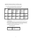
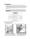
Screw
nominal dia.
Tightening
torque
Screw
Nominal dia.
Tightening torque
M4 1.47 to 1.96 N-m
(15 to 20 kgf-cm)
M8 11.8 to 14.7 N-m
(120 to 150 kgf-cm)
M5 2.94 to 3.92 N-m
(30 to 40 kgf-cm)
M10 M10 24.5 to 30.9 N-m
(250 to 315 kgf-cm)
M6 4.90 to 6.37 N-m
(50 to 65 kgf-cm)
M12 44.1 to 55.4 N-m
(450 to 565 kgf-cm)
Table 5 Tightening Torque
3.2 Inserting the VCB into the Cell
(Outside the cell →disconnected position)
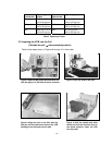
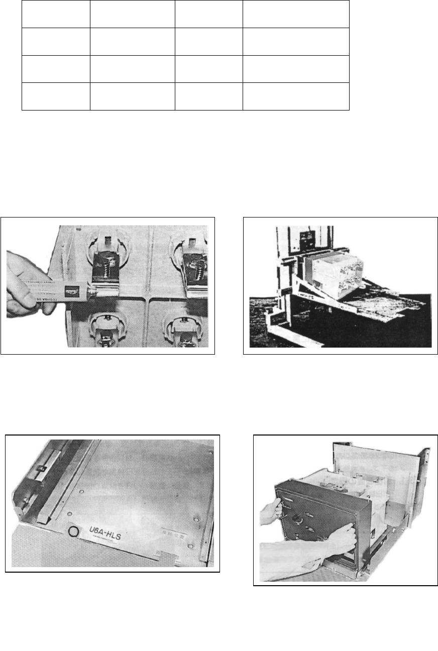
Perform the steps shown in Figures 6 through 10 in that order.
.
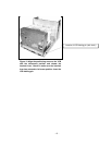
Figure 6 Open the B9 grease provided with the
unit and apply it to the ends of the six contacts.
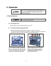
Figure 7 Place the VCB on the lifter.
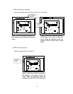
Figure 8 Align the hole on the lifter with the
lifter pin on the cubicle and remove the VCB
holding pin on the draw-out unit side.
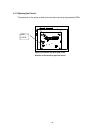
Figure 9 Hold the handle with both
hands and, with the interlock lever in
the raised position, insert the VCB
into the panel.


