


8
NOTE: DIAGRAMS & ILLUSTRATIONS NOT TO SCALE.
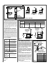
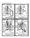
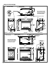
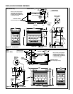
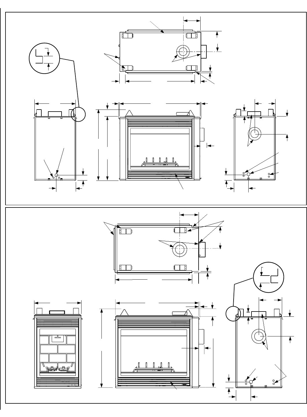
CDPF (Peninsula)
12 (305)
10
(254)
TOP VIEW
40¹⁄₈
(1019)
3¹⁄₂
(89)
⁵⁄₈
(16)
Stepped to Accept Drywall on Two Corners
FRAMING SPACERS
(Top and Side)
FINISH WALL BRACKET
(Front, back, and left edge of unit top)
6⁷⁄₈
(175)
10¹⁄₄
(260)
12
(305)
(63.5)
RIGHT SIDE VIEW
3 (76)
(13)
DETAIL OF
FINISH WALL BRACKET
FLUE
(Top or Side)
2¹⁄₂
¹⁄₂
NOTE - Unit has a factory-installed
vent seal cap and vent cover plate
(see Figures 17 and 18 on page 10)
in each flue outlet. The vent seal
cap is not shown in this figure.
24
(610)
41
(1041)
37
(940)
43⁵⁄₈
(1108)
¹⁄₂
(13)
FRONT VIEW
4 (102)
GAS INLET
ELECTRICAL
INLETS
CONTROL COMPARTMENT
ACCESS PANEL
2¹⁄₂
(63.5)
LEFT SIDE VIEW
FLUE
(Top or Side)
Figure 13
Figure 14
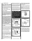
CDST (See-Through)
6⁷⁄₈
(175)
10¹⁄₄
(260)
12
(305)
12 (305)
10
(254)
(63.5)
RIGHT SIDE VIEWLEFT SIDE VIEW
TOP VIEW
3 (76)
FLUE
(Top or Side)
10¹⁄₂
(267)
FLUE
(Top or Side)
GAS INLET
ELECTRICAL
INLETS
GAS INLET
40¹⁄₈
(1019)
⁵⁄₈
(16)
Stepped to Accept Drywall on All 4 Corners
3¹⁄₂ (89)
3
(76)
ELECTRICAL
INLETS
NOTE - Unit has a factory-installed
vent sea cap and vent cover plate
(see Figures 17 and 18 on page 10)
in each flue outlet. The vent seal
cap is not shown in this figure.
FRAMING SPACERS
(Top and Both Sides)
24
(610)
FINISH WALL BRACKET
(Front and back edge of unit top)
1/2
(13)
DETAIL OF
FINISH WALL
BRACKET
3¹⁄₂ (89)
2¹⁄₂
ELECTRICAL
INLETS
CONTROL
COMPARTMENT
ACCESS PANEL
FRONT VIEW
(940)
37
41
(1041)
4 (102)
¹⁄₂ (13)
(1197)
47¹⁄₈
¹⁄₂ (13)
2¹⁄₂
(63.5)
FIREPLACE SPECIFICATIONS