


27
NOTE: DIAGRAMS & ILLUSTRATIONS NOT TO SCALE.
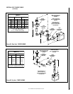
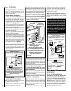
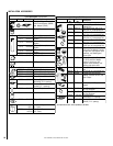
tiKnoisrevnoCsaGenaporPoTlarutaN
.oNsledoMepyTtinU.oNgolataC
TSDC
FPDC
RCDC
LCDC
tlovillim56L58
cinortcele97L58
tiKnoisrevnoCsaGlarutaNotenaporP
.oNledoMepyTtinU.oNgolataC
TSDC
FPDC
RCDC
LCDC
tlovillim27L58
cinortcele68L58
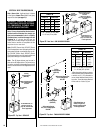
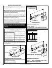
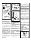
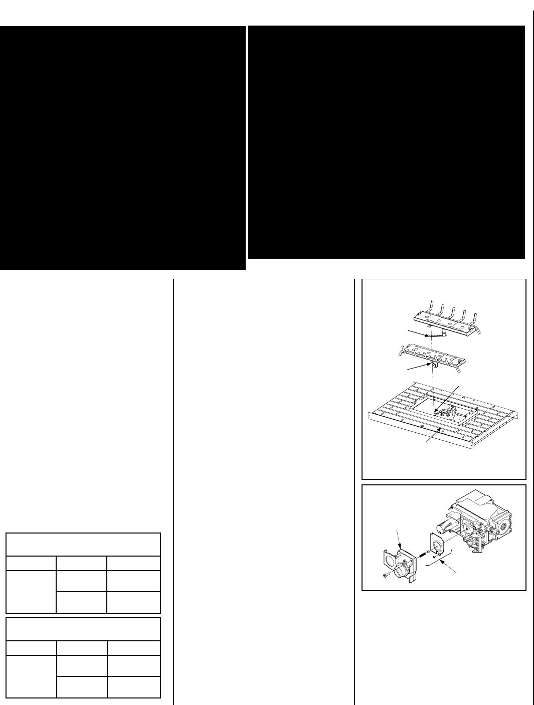
Figure 63
FRONT OF FIREPLACE
REAR BURNER
FRONT BURNER
VENTURI
TUBE ARM
VENTURI
TUBE ARM
AIR SHUTTER
ADJUSTMENT LEVER
FIREBOX SUBFLOOR
NOTE: REMOVE FRONT BURNER FIRST,
THEN REAR BURNER.
GAS CONVERSION KITS
In Canada:
THE CONVERSION SHALL BE CARRIED OUT
IN ACCORDANCE WITH THE REQUIREMENTS
OF THE PROVINCIAL AUTHORITIES HAVING
JURISDICTION AND IN ACCORDANCE WITH
THE REQUIREMENTS OF THE CAN1-B149.1
AND .2 INSTALLATION CODE.
LA CONVERSION DEVRA ÊTRE EFFECTUÉE
CONFORMÉMENT AUX RECOMMANDATIONS
DES AUTORITÉS PROVINCIALES AYANT
JURIDICTION ET CONFORMÉMENT AUX
EXIGENCES DU CODE D'INSTALLATION CAN1-
B149.1 ET.2.
Gas conversion kits are available to convert
your appliance from the use of one type of gas
to the use of another. These kits contain all the
necessary components needed to complete the
task including labeling that must be affixed to
ensure safe operation.
Kit part numbers are listed here and the following
steps detail the conversion procedure.
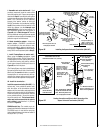
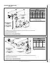
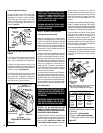
Figure 64
Pressure
Regulator
Remove
These
Components
WARNING: THIS CONVERSION KIT SHALL BE
INSTALLED BY A QUALIFIED SERVICE AGENCY IN
ACCORDANCE WITH THE MANUFACTURER'S IN-
STRUCTIONS AND ALL APPLICABLE CODES AND
REQUIREMENTS OF THE AUTHORITY HAVING JU-
RISDICTION. IF THE INFORMATION IN THESE
INSTRUCTIONS IS NOT FOLLOWED EXACTLY, A
FIRE, EXPLOSION OR PRODUCTION OF CARBON
MONOXIDE MAY RESULT CAUSING PROPERTY
DAMAGE, PERSONAL INJURY OR LOSS OF LIFE.
THE INSTALLATION IS NOT PROPER AND COM-
PLETE UNTIL THE OPERATION OF THE CONVERTED
APPLIANCE IS CHECKED AS SPECIFIED IN THE
OWNER INSTRUCTIONS SUPPLIED WITH THE KIT.
THE QUALIFIED SERVICE AGENCY PERFORMING
THIS INSTALLATION ASSUMES RESPONSIBILITY
FOR THIS CONVERSION.
AVERTISSEMENT: CET ÉQUIPEMENT DE CONVERSION
SERA INSTALLÉ PAR UNE AGENCE QUALIFIÉE DE SER-
VICE CONFORMÉMENT AUX INSTRUCTIONS DU
FABRICANT ET TOUTES EXIGENCES ET CODES
APPLICABLES DE L'AUTORISÉS AVOIR LA JURIDICTION.
SI L'INFORMATION DANS CETTE INSTRUCTION N'EST
PAS SUIVIE EXACTEMENT, UN FEU, EXPLOSION OU PRO-
DUCTION DE PROTOXYDE DE CARBONE PEUT RÉSULTER
LE DOMMAGES CAUSER DE PROPRIÉTÉ, PERTE OU
BLESSURE PERSONNELLE DE VIE. L'AGENCE QUALIFIÉE
DE SERVICE EST ESPONSABLE DE L'INSTALLATION
PROPRE DE CET ÉQUIPMENT. L'INSTALLATION N'EST
PAS PROPRE ET COMPLÉTE JUSQU'À L'OPÉRATION DE
L'APPAREIL CONVERTI EST CHÉQUE SUIVANT LES
CRITÈRES ÉTABLIS DANS LES INSTRUCTIONS DE
PROPRIÉTAIRE PROVISIONNÉES AVEC L'ÉQUIPEMENT.
Millivolt Appliances
Step 4. Refer to
Figure 64
and the instructions
provided with the kit. Using a Torx T20, remove
and discard the three pressure regulator mount-
ing screws. Remove the pressure regulator,
spring, poppet, diaphragm and bushing. Dis-
card all removed components. Ensure the
rubber gasket installed on the back of the
replacement pressure regulator is properly
positioned and install the new pressure regula-
tor using the new screws supplied with the kit.
Tighten screws to 25 In. lb. torque.
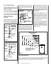
Step 1. Turn off the gas supply to the appliance.
a. Open the control compartment access panel,
by actuating the spring-loaded magnetic catches
securing the panel, gently depressing the outer
top corners of the panel until the catches "pop"
the panel free and allowing it to swing out and
down to open.
b. Locate the two (2) latches at the top of the
control compartment. To disengage the two
latches from the bottom vee-flange of the glass
enclosure panel, reach for the handles located
towards the back of the latches and pull the
handles down toward the front of the unit.
c. Swing the bottom of the door out and raise
it slightly to lift the top flange of the door frame
away from the appliance.
Step 2. Carefully remove the log set. Exercise
care as not to break the log set.
Step 3. Referring to
Figure 63
, remove the
front burner and then the rear burner.
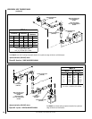
Step 5. Attach manometer to the manifold side
pressure test fitting and verify manifold pres-
sure reads 3.5 inches water column (0.87
KPa) for natural gas, and 10.0 inches water
column (2.49 kPa) for propane gas.
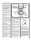
Step 6. Refer to
Figure 65 on page 28
and
remove the pilot hood assembly to access the
hexed pilot orifice. Remove and replace the
orifice with the one provided with the kit.