


5
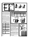
NOTE: DIAGRAMS & ILLUSTRATIONS NOT TO SCALE.
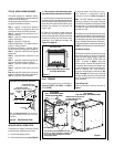
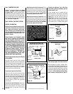
3"
(76 mm)
12"
(305 mm)
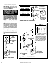
Termination
Kit
Combustible Projection
greater than 2¹⁄₂ inches in length
Horizontal Vent Termination Clearances
Combustible Projection
2¹⁄₂ inches or less in length
18"
(457 mm)
Ventilated
Soffit
Unventilated
Soffit
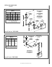
Top Louver Panel
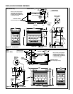
Unit Parts Identification
Control Compartment Access Panel
Figure 5 -
Side Elevation View
Figure 6
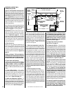
Note - See Figure 39 on page 17 for the exterior
wall recess allowances of the square horizontal
termination.
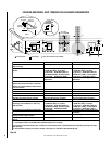
TYPICAL INSTALLATION SEQUENCE
The typical sequence of installation follows,
however, each installation is unique resulting in
variations to those described.
See the page numbers references in the follow-
ing steps for detailed procedures.
Step 1. (page 5) Construct the appliance
framing. Position the appliance within the
framing and secure with nailing brackets.
Step 2. (page 10) Route gas supply line to
appliance location.
Step 3. (page 10) Install the vent system and
exterior termination.
Step 4. (page 22) Field Wiring
A. Millivolt Appliances – The operating control
switch is factory installed.
B. Electronic Appliances – Connect 120 Vac
electrical power to the appliance receptacle.
Step 5. (page 22) Install blower kit (optional
equipment).
Step 6. (page 23) Make connection to gas
supply.
Step 7. (page 23) Install the log set, decora-
tive volcanic stone and glowing embers.
Step 8. (page 23) Checkout appliance op-
eration.
Step 9. (page 24) Install glass enclosure
panels.
Step 10. (page 24) Adjust burner primary air
shutter to achieve proper flame appearance.
Step 11. (page 25) Install the hoods.
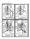
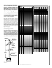
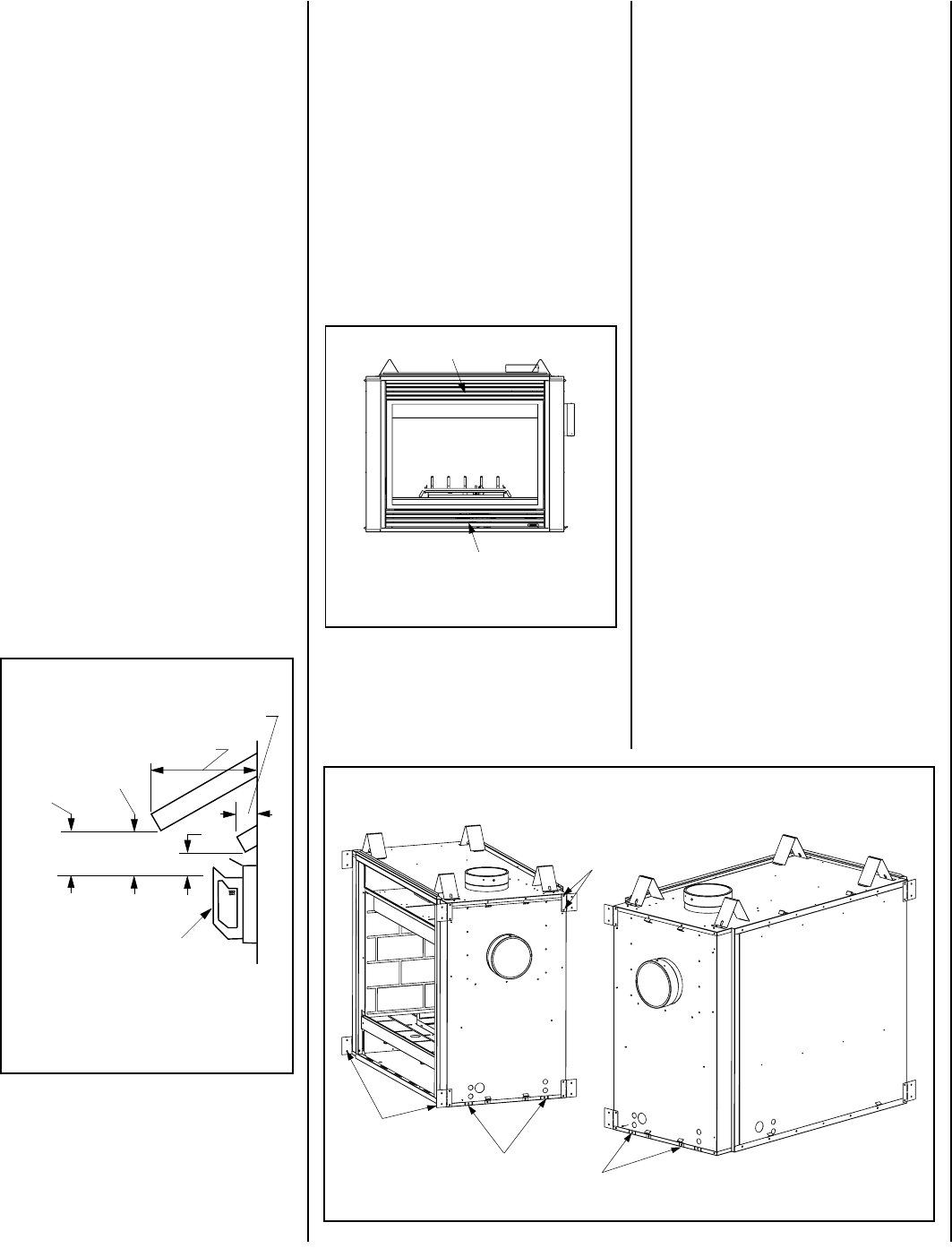
Side Nailing Flanges
The fireplace should be secured to the framing
at the side(s) and/or rear of the unit using the
factory-provided nailing flanges. Install the
nailing flanges - 8 (CDST), 4 (CDPF, CDCL and
CDCR) - as shown in
Figure 7
using the
existing screws. Position the fireplace within
the framing. When required, the flanges may
be bent 90 degrees by hand or with the assis-
tance of a hammer. Use wood screws to
secure the nailing flanges to the framing.
See
Table 2 on page 4
for clearances of framing
members to cabinet parts in the nailing flange
area. The nailing flange itself is exempt from
these clearances.
Floor Nailing Tabs
Secure the fireplace to the floor as shown in
Figure 7.
Turn tabs down and secure to the floor with
8d nails or other appropriate fasteners
on all sides of the unit which do not have
viewing glass panels.
CDST SHOWN
(CDPF - NO NAILING FLANGES
ON END WITH GLASS PANEL)
CDCL SHOWN
(FOR CDCR VIEW, INTERCHANGE SIDES)
Remove these two screws and
use them when installing
the nailing flanges.
Nailing Flanges
Figure 7
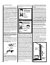
DETAILED INSTALLATION STEPS
3 - Lift the pressure relief plates and remove
the cardboard from underneath each of them.
4 - Open the control compartment access panel
by actuating the spring loaded magnetic catches
securing the panel, gently depressing the outer
top corners of the panel until the catches "pop"
the panel free, allowing it to swing out and
down to open.
5 - Open the two latches (located under the
firebox floor) securing the glass enclosure
panel. Remove the panel by tilting it outward at
the bottom and lifting it up. Set the door aside
protecting it from inadvertent damage.
See
Figure 57 on page 24.
The appliance is shipped with all gas controls
and components installed and pre-wired.
1 - Remove the shipping carton.
2 - Remove the top louver panel
(see Figure 6)
.
Note: The CDST fireplace is installed in the
framing by cocking it at an angle, fitting the
collar side in first and then twisting and pushing
the other side in. To minimize the obstruction,
it is helpful to make sure the cap is removed
from the rear collar.
If the appliance is to be elevated above floor level,
a solid continuous platform must be constructed.
Headers may be in direct contact with the appli-
ance top spacers but must not be supported by
them or notched to fit around them. All construc-
tion above the appliance must be self supporting,
DO NOT use the appliance for structural support.
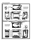
All framing details must allow for a mini-
mum clearance to combustible framing
members as shown in
Table 2 on page 4
.
Step 1. FRAMING
Frame these appliances as illustrated in
Figures 9 (CDST), 10 (CDPF), 11 (CDCL)
or 12 (CDCR).