


17
NOTE: DIAGRAMS & ILLUSTRATIONS NOT TO SCALE.
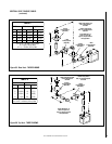
M. Install the termination -
J. Assemble vent run to exterior wall - If not
previously measured, locate the center of the
vent at the exterior wall. Prepare an opening as
described in Step B. Assemble the vent system
to point where the terminus of the last section is
within 7¹⁄₂ in. (191 mm) to 11³⁄₄ in. (298 mm)
inboard of the exterior surface to which the
SV4.5HT termination is to be attached, see
Fig-
ure 39
. If the terminus of the last section is not
within this distance, use the telescopic vent
section SV4.5LA, as the last vent section. For
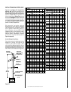
wall thicknesses greater than that shown in
Figure 38
, refer to
Table 3 on page 18
. This table
lists the additional venting components needed
(in addition to the termination and adapter) for a
particular range of wall thicknesses.
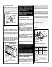
K. Attach termination adapter - Attach the
adapter (adapter - SV4.5RCH - provided with
the termination) to the vent section or tele-
scoping vent section), elbow or appliance col-
lar as shown in
Figure 38
in the same manner
as any SV4.5 vent component (refer to Step E).
L. Install Firestop/Spacer at exterior wall -
When using the square termination, install
SV4.5HF (Secure Vent), SF4.5HF (Secure Flex)
Firestop/Spacer over the opening at the exte-
rior side of the framing, long side up, with the
3 inch spacer clearance at the top as shown in
Figure 38
, and nail into place.
(The Firestop/Spacer may also be installed over
the opening at the interior side of the framing.)
When using the round termination, a separate
firestop/spacer is not required since this ter-
mination has integral spacers which provide
the same function as a separate firestop/spacer.
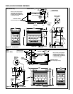
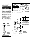
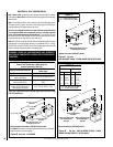
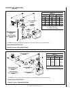
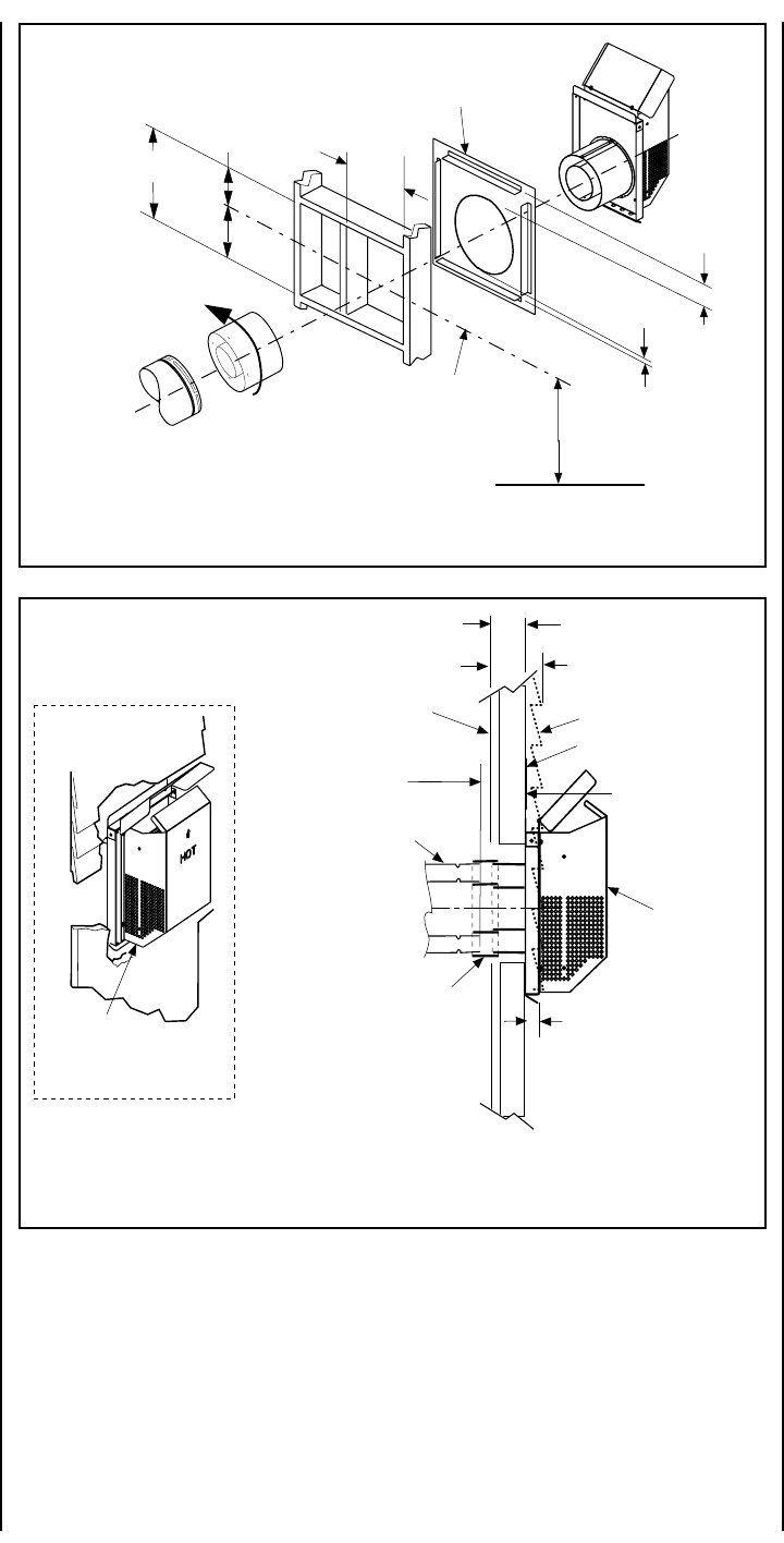
Install the square termination (SV4.5HT)- For
the last step , from outside the exterior wall,
slide the collars of the termination onto the
adapter until the termination seats against the
exterior wall surface to which it will be attached.
Orient the housing of the termination with the
arrow pointed upwards. Secure the termina-
tion to the exterior wall. The horizontal termi-
nation must not be recessed into the exterior
wall or siding by more than the 1 ¹⁄₄" (32 mm)
as shown in
Figure 39
.
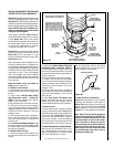
SFHRK Snorkel Cap –The snorkel cap is de-
signed to be fitted into a basement window box.
The SFHRK cap is for use with flex vent pipe.
Vertical distance between the inlet and outlet of
the cap is 28 in. (711 mm).
*1¹⁄₄" Maximum Recess of
Square Termination into
Exterior Finishing Material
Exterior Surface of
Framing
7¹₂ in. (191 mm) to
11³₄ in. (298 mm)
Exterior Surface of Siding
Minimum wall thickness
*5 in. (127 mm)
Interior Surface of
Finished Wall
Maximum wall thickness
11³₄ in. (298 mm)
Maximum Extent of
Vent Run Sections
Relative to Exterior
Surface of Framing
Last Vent Section. Use
Telescopic Vent
Section (SV4.5LA), If
Necessary
Adapter
SV4.5RCH
SV4.5HT
Square
Termination
*Cut termination collar for wall
thicknesses less than 7¹₂ in. (191 mm)
Note - Firestop/Spacer (SV4.5HF)
required but not shown for clarity.
Note - When using Secure Flex,
use Firestop/Spacer SF4.5HF
Siding
Stucco
SV4.5HT
Square Termination
Stucco and Siding
Installation shown
Figure 38
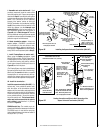
Figure 39
Installing the Square Horizontal Termination (SV4.5HT)
Venting Connection and Exterior Wall Recessing of the
Square Horizontal Termination (SV4.5HT)
*When using Secure Flex, use
Firestop/Spacer SF4.5HF
Firestop/Spacer (SV4.5HF) shown
on the exterior side of the wall. It
may also be installed on the
interior side.
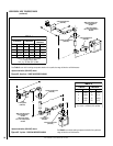
10¹⁄₂"
(267 mm)
7"
(178)
5¹⁄₈"
(130 mm)
12¹⁄₈"
(308 mm)
Note: Centerline of Vent Piping
is NOT the Same as the
Centerline of the Framed
Opening.
6 to 48 inch Vent Section,
Telescopic vent section,
Elbow or Appliance Collar
See Figure 9 (CDST), 10
(CDPF), 11 (CDCL) or 12
(CDCR) on page 7 for Min.
Distance to Base of Appliance.
Base of Appliance
3"
(76 mm)
1"
(25.4 mm)
Adapter
SV4.5RCH
SV4.5HT
Termination