


10
NOTE: DIAGRAMS & ILLUSTRATIONS NOT TO SCALE.
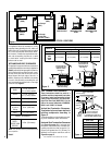
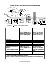
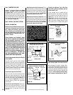
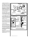
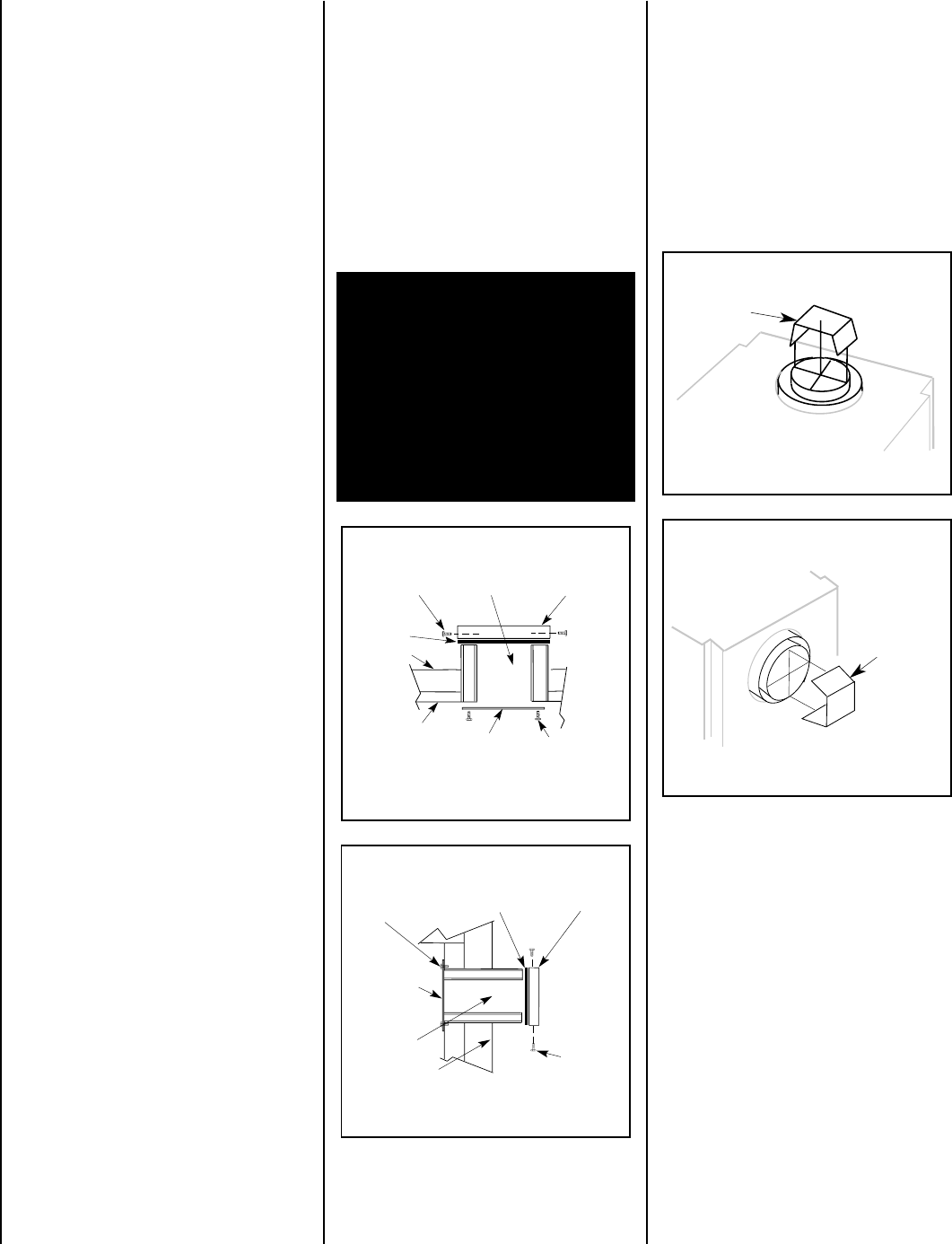
VENT RESTRICTOR INSTALLATION
(REAR VENT)
RESTRICTOR
APPLIANCE SIDE
VENT OUTLET
VENT RESTRICTOR INSTALLATION
(TOP VENT)
RESTRICTOR
APPLIANCE TOP
VENT OUTLET
Figure 19
Figure 20
Select Venting System - Horizontal or Vertical
With the appliance secured in framing, deter-
mine vent routing and identify the exterior termi-
nation location. The following sections describe
vertical (roof) and horizontal (exterior wall) vent
applications. Refer to the section relating to your
installation. A list of approved venting compo-
nents is shown in the two tables on page 27.
A vent restrictor may be needed with this
appliance, install a vent restrictor (provided)
in the appliance top flue outlet as shown in
Figure 19
or side flue outlet as shown in
Figure 20
when vertically terminating the vent
system above the roof. It may be installed
either from inside or outside the unit, in the
inner fireplace collar. It is press-fitted in place.
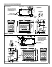
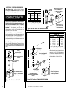
Step 2. ROUTING GAS LINE
Route a ¹⁄₂" (13 mm) gas line as shown in
Figure
9 (CDST), 10 (CDPF), 11 (CDCL) or 12 (CDCR)
on pages 8 and 9
. Gas lines must be routed,
constructed and made of materials that are in
strict accordance with local codes and regula-
tions. All appliances are factory-equipped with
a flexible gas line connector and ¹⁄₂ inch shutoff
valve. (See step 6 on page 23).
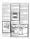
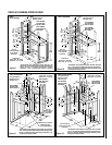
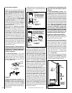
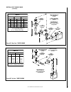
TOP VENT SEAL CAP & COVER PLATE
REMOVAL WHEN USING THE TOP VENT
VENT SEAL CAP
FIREBOX TOP
CABINET TOP
SECURING SCREWS
VENT COVER PLATE
TOP VENT
COVER PLATE
SECURING SCREW
CROSS SECTION
(INSIDE UNIT)
(OUTSIDE UNIT)
INSULATION
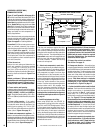
VENT SEAL CAP
SECURING
SCREWS
CROSS SECTION
REAR VENT
COVER PLATE
SECURING SCREWS
CABINET BACK
(INSIDE UNIT)
(OUTSIDE UNIT)
INSULATION
COVER PLATE
REAR VENT SEAL CAP & COVER PLATE
REMOVAL WHEN USING THE REAR VENT
Figure 17
Figure 18
Step 3. INSTALL THE VENT SYSTEM
GENERAL INFORMATION
These instructions should be used as a guide-
line and do not supersede local codes in any
way. Install vent according to local codes,
these instructions, the current National Fuel
Gas Code (ANSI-Z223.1) in the USA or the
current standards of CAN/CGA-B149.1 and -
B149.2 in Canada.
These fireplaces are designed, tested
and listed for operation and installation
with, and only with, Secure Vent™ Direct
Vent System Components, Secure Flex™
Flexible Vent Components manufactured
by Security Chimneys International and
Z-FLEX™ Model GA Venting Systems listed
to UL1777 and ULCS635 manufactured by
Flexmaster Canada Limited. These ap-
proved vent system components are la-
beled for identification.
DO NOT use
any other manufacturer's vent com-
ponents with these appliances.
These fireplaces must be vented directly
to the outside.
The vent system must not service multiple
appliances, and must never be connected to a
flue serving a solid fuel burning appliance. The
vent pipe is tested to be run inside an enclo-
sure (such as a chase). There is no require-
ment for inspection openings in the enclosure
at any of the joints in the vent pipe.
Preparing the Appliance Vent Collar
Each of the unit's two vent collars are sealed
with a cover plate and a seal cap. The cover
plate and seal cap must be removed from the
vent collar being used. Refer to
Figure 17
for
top vent usage and
Figure 18
for rear, and the
following steps to prepare the appropriate
collar for use.
From the vent collar being used, remove the
two screws securing the vent cap. Twist the
cap counterclockwise. Pull it away from the
unit and discard, along with the piece of
insulation.
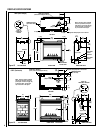
Preparing the Appliance Top or Rear Vent
Outlet when vertically terminating the vent
system above the roof
When the top vent collar is being used, from
inside the firebox, loosen the two screws in the
keyhole slots of the cover plate and remove the
remaining two cover plate securing screws.
Remove and discard the cover plate. Reinstall
and securely tighten all four screws.
When the rear vent collar is being used, from
inside the firebox, loosen the two screws in the
keyhole slots of the cover plate and remove the
remaining two cover plate securing screws.
Remove and discard the cover plate. Reinstall
and securely tighten all four screws.
WARNING: FAILURE TO REINSTALL
AND SECURELY TIGHTEN COVER PLATE
SCREWS COULD RESULT IN LEAKAGE
OF FLUE PRODUCTS INTO THE LIVING
SPACE. VENT COVER PLATE AND VENT
SEAL CAP MUST REMAIN SECURELY
INSTALLED ON UNUSED VENT COLLAR.
FAILURE TO DO SO COULD RESULT IN
LEAKAGE OF FLUE PRODUCTS INTO
LIVING SPACE.