


23
NOTE: DIAGRAMS & ILLUSTRATIONS NOT TO SCALE.
Figure 52
Figure 54
Figure 53 -
GAS CONNECTION
Turn on gas supply and test for gas leaks using
a soapy water solution. Never use an open
flame to check for leaks.
A. Mix a 50% dish soap, 50% water solution.
B. Light the appliance (refer to the lighting
instructions provided in the Homeowner's Care
and Operation Instructions).
C. Brush all joints and connections with the
soapy water solution to check for leaks. If bubbles
are formed, or gas odor is detected, turn the gas
control knob to the “OFF” position. Either tighten
or refasten the leaking connection and retest as
described above.
D. When the gas lines are tested and leak
free, observe the individual tongues of flame
on the burner. Make sure all ports are open
and producing flame evenly across the
burner. If any ports are blocked, or partially
blocked, clean out the ports.
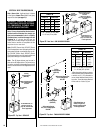
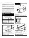
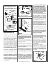
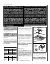
Step 6. CONNECTING GAS LINE
Make gas line connections. All codes require a
shut-off valve mounted in the supply line.
Fig-
ure 53
illustrates two methods for connecting
the gas supply. The flex-line method is accept-
able in the U.S., however, Canadian require-
ments vary depending on locality. Installation
must be in compliance with local codes.
These appliances are equipped with a gas flex
line for use (where permitted) in connecting the
unit to the gas line. A gas flex line is provided
to aid in attaching the direct vent appliance to
the gas supply. The gas flex line can only be
used where local codes permit. See
Figure 53
for flex line description. The flex line is rated for
both natural and propane gas. A manual shut
off valve is also provided with the flex line.
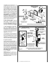
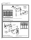
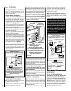
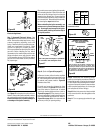
The gas control valve is located in the lower
control compartment. To access the valve pro-
ceed as follows: Open the control compart-
ment access panel
(Figure 54)
by actuating the
spring-loaded magnetic catches securing the
panel, gently depressing the outer top corners
of the panel until the catches "pop" the panel
free, allowing it to swing out and down to open.
The millivolt control valve has a ³⁄₈"
(10 mm) NPT thread inlet port. The electronic
control valve has a ¹⁄₂" (13 mm) NPT thread inlet
port and is fitted with a ¹⁄₂" x ³⁄₈" (13 mm x
10 mm) NPT fitting.
Secure all joints tightly using appropriate
tools and sealing compounds (ensure pro-
pane resistant compounds are used in pro-
pane applications).
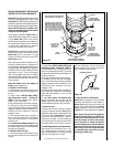
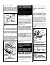
The top ³⁄₈" (10 mm) at the pilot generator
(thermopile) and the top ¹⁄₈" min (tip) of the
quick drop out thermocouple should be en-
gulfed in the pilot flame. The flame should
project 1" (25 mm) beyond the hood at all three
ports
(Figure 55)
.
Millivolt Appliance Checkout
The pilot flame should be steady and, not lifting
or floating. Flame should be blue in color with
traces of orange at the outer edge.
Step 7. INSTALLING LOG SET, VERMICU-
LITE AND CERAMIC FIBER CHUNKS
The log set, a bag of decorative volcanic stone
and a bag of glowing embers (rockwool) is
supplied in the unit. Refer to the Homeowner's
Care and Operating Instructions for detailed
placement instructions for the logs, decorative
volcanic stone and glowing embers.
Step 8. CHECKING APPLIANCE OPERATION
With gas line installed, run initial system
checkout before closing up the front of the
unit. Follow the pilot lighting instructions
provided in the Homeowner's Care and Op-
eration Instructions. For piezo ignitor loca-
tion see
Figure 54
(millivolt appliances only).
Note: Lighting instructions may also be found
on the pull out lighting instruction labels at-
tached to the gas control valve.
To access the
label, see the procedure on the previous page
described for accessing the gas control valve.
When first lighting the appliance, it will take
a few minutes for the line to purge itself of
air. Once purging is complete, the pilot and
burner will light and operate as indicated in
the instruction manual. Subsequent lightings
of the appliance will not require such purg-
ing. Inspect the pilot flame (remove logs, if
necessary, handling carefully).
Figure 55
Replace logs after pilot inspection.
To light the burner: turn “ON” the unit-mounted
ON/OFF switch or the wall-mounted ON/OFF
switch or the thermostat (depending on the
type of control installed), and rotate the gas
valve control knob counterclockwise to the
“ON” position.
Gas
Stub
¹₂" x
³₈" Flare
Shut-Off Valve
³₈" Flex Tubing
³₈" NPT x ³₈
Flare Fitting
³₈" Nipple
³₈"
Union
³₈" Close Nipple
³₈" Shut-Off Valve
¹₂
x ³₈ "
Reducer
Gas
Valve
Gas Flex Line Connector
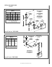
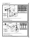
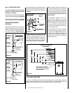
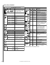
1. If any of the original wire as supplied must be replaced,
1. it must be replaced with Type AWM 105°C – 18 GA. wire.
2. 120V, 60Hz – Less than 3 amps.
BK
Transf.
120 V.
24 V
Factory Wired Field Wired
BL
Electronic Wiring Diagram (Honeywell)
Showing the Blower Wiring for the Optional
FBK-250 Kits
R
WH
BL
OPT
BLOWER
G
W
120
VAC.
BK
W
Gas Valve
B
R
IGNITER
PILOT
ASSEMBLY
BK
G
Outlet Box Green
Ground Screw
Hot side of Outlet
Schematic Representation Only
*ON/OFF Switch
(Integral with Gas Valve)
White Wire
To Opposite
Side
Optional FBK-250
Module
*Leave the ON/OFF switch, which is integral
with the gas valve, in the ON position.
G
OPTIONAL APPLIANCE-MOUNTED ON/OFF SWITCH
OR OPTIONAL WALL SWITCH OR OPTIONAL
THERMOSTAT OR OPTIONAL REMOTE RECEIVER
Piezo Ignitor
Gas Valve
Control
Compartment
Access panel
Hinge Pin
¹⁄₈" Min
(3 mm)
Thermocouple
Ignitor Rod
Hood
³⁄₈" Min
(9 mm)
Thermopile
MILLIVOLT HONEYWELL
Pilot
Nozzels