


4
NOTE: DIAGRAMS & ILLUSTRATIONS NOT TO SCALE.
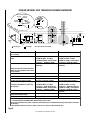
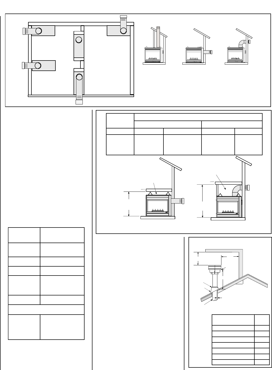
hctiPfooR
H
)teef(
21/6ottalF0.1
21/7ot21/6revO52.1
21/8ot21/7revO5.1
21/9ot21/8revO0.2
21/01ot21/9revO5.2
21/11ot21/01revO52.3
21/21ot21/11revO0.4
KCAB
)mm31(.ni2/1
srecaps)mm0(.ni0
SEDIS
)mm31(.ni2/1
srecaps)mm0(.ni0
SRECAPSPOT)mm0(.ni0
ROOLF)mm0(.ni0
mottoBmorF
ottinUfo
gnilieC
)mm6261(.ni46
TNEV*)mm4.52(.ni1
SECNARAELCECIVRES
GNIWEIV
-SEDIS
KCABTNORF(
)EDISRO
)sretem9.0(.teeF3
12
X
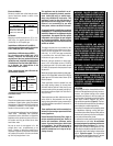
Roof Pitch is X/12
2 FT
MIN.
2 FT MIN.
Lowest
Discharge
Opening
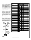
H*
*H = MINIMUM HEIGHT FROM ROOF TO
LOWEST DISCHARGE OPENING OF VENT
TERMINATION HEIGHTS FOR VENTS ABOVE
FLAT OR SLOPED ROOFS
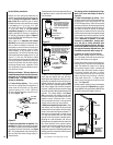
Horizontal Overhang
Vertical
Wall
Vent
Termination
Storm Collar
Concentric
Vent Pipe
Flashing
1 inch (25.4 mm) Minimum
Clearance to Combustibles
Figure 4
Figure 2
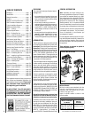
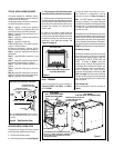
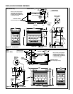
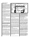
APPLIANCE AND VENT CLEARANCES
The appliance is approved with zero clearance to
combustible materials on all sides (as detailed in
Table 2 )
, with the following exception: When the
unit is installed with one side flush with a wall,
the wall on the other side of the unit must not
extend beyond the front edge of the unit. In
addition, when the unit is installed in the middle
of a room, the side walls surrounding the unit
must not extend beyond the front or rear edge
of the unit. See
Figure 2
.
The appliance should be mounted on a fully
supported base extending the full width and
depth of the unit. The appliance may be located
on or near conventional construction materi-
als. However, if installed on combustible mate-
rials, such as carpeting, vinyl tile, etc., a metal
or wood barrier covering the entire bottom
surface must be used.
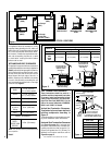
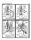
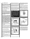
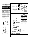
Figure 3
TYPICAL LOCATIONS
VERTICAL VENT
See-Through
(CDST)
Corner - Left
(CDCL)
Corner - Right
(CDCR)
Peninsula
(CDPF)
HORIZONTAL VENT
- REAR
See-Through
(CDST) -
one side flush
with a wall
HORIZONTAL VENT
- TOP
*
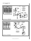
Note: 3 in. (75 mm) above any horizontal/inclined
vent component.
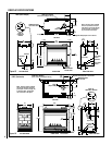
Table 2
.oNledoM
)mm(sehcnithgieHflehS
woblEeergeD09enOhtiw-tneVpoTkcaBehttuOthgiartS-tneVraeR
tneVeruceSxelFeruceStneVeruceSxelFeruceS
TSDC
FPDC
RCDC
LCDC
2/135)9531(4/155)3041(8/114)5401(8/114)5401(
VENT TERMINATION CLEARANCES
These instructions should be used as a
guideline and do not supersede local codes
in any way. Install vent according to local
codes, these instructions, the current Na-
tional Fuel Gas Code (ANSI-Z223.1) in the
USA or the current standards of CAN/CGA-
B149.1 and -B149.2 in Canada.
Vertical Vent Termination Clearances
Terminate single vent caps relative to
building components according to
Figure 4.
Terminate multiple vent terminations accord-
ing to the installation codes listed above.
Horizontal Vent Termination Clearances
See
Figure 5 on page 5
for horizontal vent
termination clearances to any overhead com-
bustible projection less than or equal to 2 ¹⁄₂"
(64 mm) and greater than 2¹⁄₂" (64 mm). For
additional vent location restrictions refer to
Figure 8 on page 6
.
Shelf Above Fireplace
With Rear Venting
Do not insulate the
space between the
appliance and the
area above it.
Shelf Height
(see table)
Shelf Above Fireplace
With Top Venting
Do not insulate the
space between the
appliance and the
area above it.
Shelf Height
(see table)