


22
NOTE: DIAGRAMS & ILLUSTRATIONS NOT TO SCALE.
Step 4. FIELD WIRING
Refer to Section A for millivolt appliances and
Section B for electronic appliances. The gas
valve is set in place and pre-wired at the
factory on both models.
Note: The gas valve ON/OFF switch is shown in
Figure 51, or 52 on page 23. It is integral with
the gas valve and should be set to the ON
position.
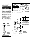
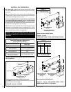
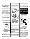
A. Millivolt Wiring
(See Figure 49 )
–
1. Select any of the following optional con-
trols: appliance-mounted (rocker switch) or
wall-mounted switch, thermostat, or one of
the optional remote control kits. If appliance-
mounted ON/OFF control is selected mount it
in the gas valve mounting bracket.
2. If wall-mounted ON/OFF control or thermo-
stat is selected mount it in a convenient loca-
tion on a wall near the fireplace.
3. Wire the control switch within the millivolt
control circuit using the 15 feet of 2 conductor
wire supplied with the unit.
Caution: do not connect the optional wall
switch to a 120V power supply.
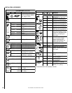
4. Alternatively, the appliance may be oper-
ated without the use of the controls indicated
in step 1, solely by manipulating the gas valve
control knob. In order to use this method,
twist the free ends of the two conductor wire
(located in the bottom compartment of the
unit) together as shown in
Figure 49
.
Note: The supplied 15 feet of 2 conductor wire
has one end of each conductor connected to the
gas valve circuit and the other end of each
conductor placed loose inside the bottom com-
partment of the unit.
Figure 49
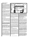
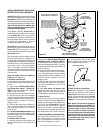
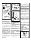
10. After wiring is complete, reinstall the outlet
receptacle, junction box/outlet receptacle as-
sembly; install the field-provided the metal
junction box cover plate.
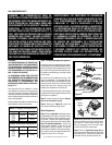
Receptacle, Junction Box and
Cover Plate Installation
Figure 50
2. Open the control compartment access panel by
actuating the spring-loaded magnetic catches se-
curing the panel, gently depressing the outer top
corners of the panel until the catches "pop" the panel
free, allowing it to swing out and down to open.
3. Remove the junction box/outlet receptacle
assembly by removing the securing screw at
the front right corner of the unit. See
Figure 50.
(The left and right designations used here are
reversed in CDCR applications.)
B. Electronic Wiring
(See either Figure 51, or 52 on page 23)
Note: The electronic appliance must be con-
nected to the main power supply.
1. Route a 3-wire 120Vac 60Hz 1ph power
supply to the appliance junction box.
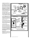
4. Remove the outlet receptacle from the junc-
tion box by removing the two securing screws.
5. Install a field-provided strain relief in the
cabinet knockout opening for the protection of
the power supply wires.
6. Connect the power supply wires to the receptacle
as shown in
Figure 51, or 52 on page 23.
7. Connect the ground supply wire to the
green wire attached to the outlet receptacle's
green ground screw.
8. Install a wall-mounted ON/OFF switch or
thermostat (not supplied) in a convenient lo-
cation near the fireplace.
9. Wire the wall-mounted ON/OFF switch or
thermostat to the low voltage circuit as shown
in
Figure 51, or 52 on page 23.
Note: The supplied 15 feet of 2 conductor wire
has one end of each conductor connected to the
gas valve circuit and the other end of each
conductor placed loose inside the bottom com-
partment of the unit.
Step 5. WIRING - OPTIONAL FORCED
AIR BLOWER KIT
FBK-100, FBK-200 and FBK250 Kits
(See Figure 51 for FBK-100, FBK-200 and
Figure 52 on page 23 for FBK-250 wiring)
-
An electrical receptacle is provided for the
installation of the FBK-100, FBK-200 and
FBK-250 forced air blower kits. Electrical
power must be connected to this receptacle
in order to operate these blowers. Install the
blower kits according to the installation in-
structions provided with the kits.
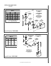
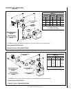
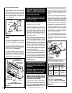
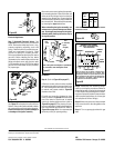
Figure 51
Millivolt Wiring Diagram
If any of the original wire as supplied must be replaced,
it must be replaced with Type AWM 105°C, 18 GA. wire.
Thermopile
TH
TP
TH
TP
*TWIST WIRES “A” AND “B” TOGETHER TO OPERATE UNIT
SOLELY BY MANIPULATING THE GAS VALVE CONTROL KNOB;
OR CONNECT WIRES TO OPTIONAL UNIT-MOUNTED ON/OFF
SWITCH OR WALL-MOUNTED ON/OFF SWITCH OR
THERMOSTAT TO OPERATE UNIT.
*UNIT-MOUNTED ON/OFF SWITCH (Accessory Option)
OR WALL-MOUNTED ON/OFF SWITCH (Accessory Option)
OR THERMOSTAT (Accessory Option)
OR REMOTE CONTROL RECEIVER (Accessory Option)
AB
1. If any of the original wire as supplied must be replaced,
1. it must be replaced with Type AWM 105°C – 18 GA. wire.
2. 120V, 60Hz – Less than 3 amps.
BK
Junction Box
Transf.
120 V.
24 V
Factory Wired Field Wired
BL
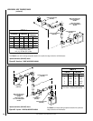
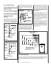
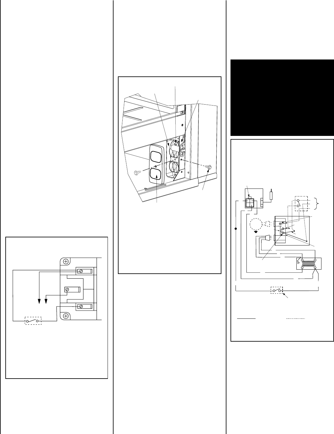
Electronic Wiring Diagram (Honeywell)
Showing the Blower Wiring for the Optional FBK-
100 and FBK-200 Kits
R
W
BL
OPT
BLOWER
G
W
*OPTIONAL
ACCESSORY
SWITCH
120
VAC.
BK
W
Gas Valve
B
R
IGNITER
PILOT
ASSEMBLY
Break Off
Tab
BK
G
*Blower speed control switch is provided in FBK200 blower kit.
Outlet Box
Green Ground
Screw
Hot side of Outlet
Schematic Representation Only
**ON/OFF Switch (Integral
with Gas Valve)
**Leave the ON/OFF switch, which is integral
with the gas valve, in the ON position.
OPTIONAL APPLIANCE-MOUNTED ON/OFF SWITCH
OR OPTIONAL WALL SWITCH OR OPTIONAL
THERMOSTAT OR OPTIONAL REMOTE RECEIVER
Red
pigtail
Black
pigtail
White Wire
to Opposite
Side
G
CDST, CDPF
AND CDCL OUTLET RECEPTACLE SHOWN.
CDCR HAS THE OUTLET RECEPTACLE LOCATED IN
THE LEFT CORNER OF THE UNIT
VIEW OF RIGHT BOTTOM CORNER OF UNIT
OUTLET RECEPTACLE
JUNCTION BOX
MOUNTING BRACKET
JUNCTION BOX
JUNCTION BOX
SECURING SCREW
FIELD-PROVIDED METAL JUNCTION BOX
COVER PLATE WITH SCREW
IMPORTANT: Ground supply lead must be
connected to the wire attached to the green
ground screw located on the outlet recep-
tacle. See
Figures 51, and 52 on page 23
.
Failure to do so will result in a potential safety
hazard. The appliance must be electrically
grounded in accordance with local codes or,
in the absence of local codes, the National
Electrical Code, ANSI/NFPA 70-(latest edi-
tion). (In Canada, the current CSA C22-1
Canadian Electrical Code.)