


28
NOTE: DIAGRAMS & ILLUSTRATIONS NOT TO SCALE.
The manufacturer reserves the right to make changes at any time, without notice, in design, materials, specifications, prices and also to discontinue colors, styles and products.
Consult your local distributor for fireplace code information.
LHP
1110 West Taft Avenue • Orange, CA 92865
Printed in U.S.A. © 2002 by Lennox Hearth Products
P/N 700,001M REV. H 09/2005
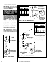
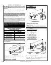
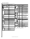
Pilot
Orifice
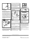
Retaining
Clip
Ignitor
Assembly
Pilot
Assembly
Pilot
Orifice
Flare Nut
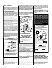
Note: If the ignitor is damaged, a replacement
kit is available, order Catalog No. 87L54.
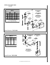
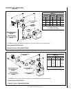
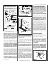
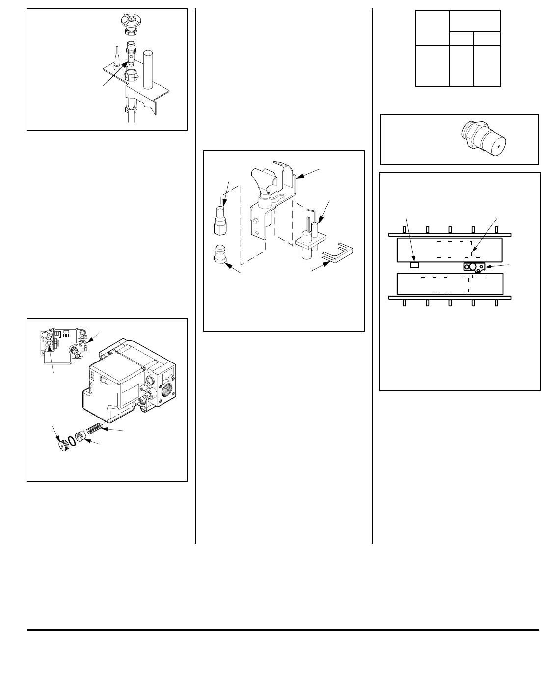
BURNER POSITIONING
REAR BURNER
FRONT BURNER
PILOT
BURNER
Note: The burners are not identical. Position them so
that the circular burner ports run as shown. Note
especially the vertical run of ports relative to the pilot
burner. Bracket A on the rear burner will interfere with
the pilot burner if an attempt is made to install the
rear burner in the front burner’s position.
BRACKET A
BURNER
PORTS
NOTE: INSTALL REAR BURNER FIRST,
THEN FRONT BURNER.
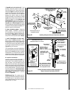
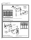
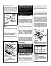
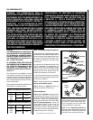
Spring
Adjusting
Screw
Slotted
Cap
PSI
OFF
I
ON
CONTROL
IG
N
ITE
Manifold
Pressure
Test Port
Inlet Pressure Test Port
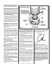
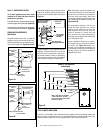
ledoM
.oN
*ezisecifirO
.taN.porP
TSDC
FPDC
RCDC
LCDC
44#55#
Figure 67
Figure 66
Figure 68
Figure 65
Figure 69
Remove the screw securing the pilot assembly
to its mounting bracket. Back off the flare nut
at the end of the pilot gas line to free the pilot
assembly from the gas line. Remove the pilot
orifice and replace it with the one provided with
the conversion kit. Reinstall the pilot assembly
by reversing the steps detailed here.
When reinstalling the ignitor assembly, use
extreme care to prevent damage and break-
age. Do not apply any leverage to the ignitor
assembly while restoring the retainer clip to
its original position.
* Each model has two burners. Each burner contains
one of these orifices.
NOTE: DIAGRAMS & ILLUSTRATIONS NOT TO SCALE.
Electronic Appliances
Step 7. Honeywell Electronic Valves - See
Figure 66
and the instructions provided with
the kit. Remove the slotted cap screw, o-ring,
pressure-regulating adjusting screw and
spring. Retain all parts for possible later use.
Install new components from the kit. Black
cap and red spring for propane gas units.
Silver cap and stainless steel spring for natural
gas units. Before installing the cap, attach
manometer to the manifold side pressure test
fitting and adjust screw until pressure reads
3.5 inches water column (0.87 kPa) for natural
gas, and 10.0 inches water column (2.49 kPa)
for propane gas.
Step 9. Reassemble the remaining compo-
nents by reversing the procedures outlined in
the preceding steps. Use pipe joint compound
or Teflon tape on all pipe fittings before install-
ing (ensure propane resistant compounds are
used in propane applications, do not use pipe
joint compounds on flare fittings).
Step 10. Attach the conversion label provided
in the conversion kit to the rating plate on the
appliance.
Step 11. Turn on gas supply and test for gas
leaks.
See
Figure 67
and replace the pilot orifice as
follows: Remove the ignitor assembly retainer
clip, and carefully remove the ignitor assembly.
Exercise extreme care to prevent damage to
or breakage of the ignitor assembly.
All Models
Step 8. (Refer to
Figure 63 on page 27
)
A. Remove the two orifices from the manifold
and replace them with the ones provided in the
kit. The following table shows the orifice sizes
for natural and propane models
. Figure 68
illustrates the orifice.
B. Install rear burner first, followed by front
burner, as shown in
Figure 69
. Ensure that the
arm of the venturi of each burner is hooked
onto the air shutter adjustment lever (refer to
Figure 63 on page 27).
The primary air open-
ing can be adjusted by rotating the adjustment
lever from beneath the firebox floor. Refer to
Figure 58 on page 23
for the recommended
minimum primary air opening setting.