


25
NOTE: DIAGRAMS & ILLUSTRATIONS NOT TO SCALE.
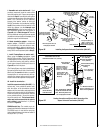
Combustible
Finished Wall
Materials
This Area Must Remain Clear
of Combustible Materials
Top of Appliance
1" Min
(25 mm)
Combustible
Wall Framing
Spacer
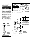
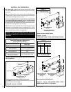
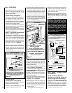
Clean Face Models
Top of Door Frame
Hood must be installed as shown.
Radiant panel
Drywall
Bracket/Spacer
Combustible Wall
Framing
Top of Appliance
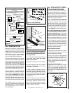
Louver Face Models
Top of Door Frame
Hood must be installed as shown.
Louvers
Combustible
Finished Wall
Materials
This Area Must Remain Clear
of Combustible Materials
1" Min
(25 mm)
Combustible
Wall Framing
Spacer
Drywall
Bracket/Spacer
Combustible Wall
Framing
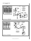
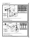
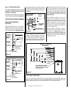
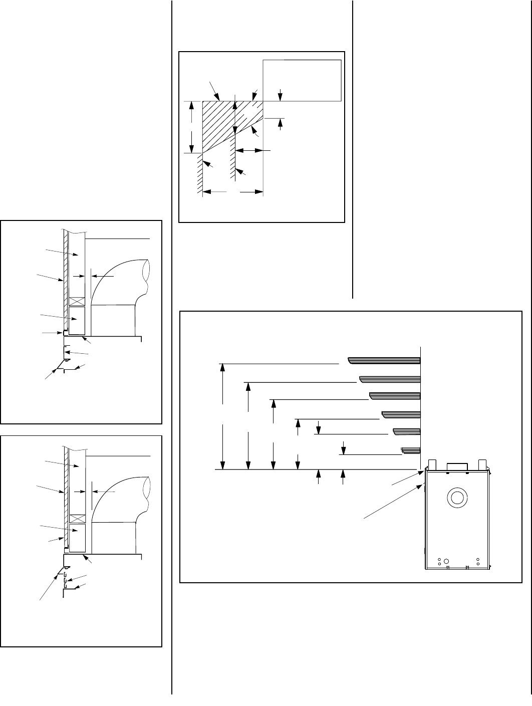
12 (305) MANTEL
10 (254) MANTEL
8 (203) MANTEL
6 (152) MANTEL
4 (102) MANTEL
4
(102)
14
(356)
12
(305)
10
(254)
2 (51) MANTEL
TOP OF
APPLIANCE
6
(152)
NOTE - Hood shown as positioned
in flush faced model. The hood
position in the louvered front model
is higher than shown.
8
(203)
MANTEL CLEARANCES
Inches (mm)
Figure 59
Figure 60
Figure 62
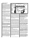
COLD CLIMATE INSULATION
If you live in a cold climate, seal all cracks around your appliance with noncombustible material and
wherever cold air could enter the room. It is especially important to insulate outside chase cavity
between studs and under floor on which appliance rests, if floor is above ground level.
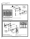
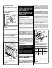
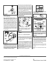
Combustible materials may project beyond the
sides of the fireplace opening as long as they
are kept within the shaded areas illustrated in
Figure 61
.
Figure 61
A hearth extension is not required with this
appliance. If a hearth extension is used, do not
block the control compartment access panel.
Any hearth extension used is for appearance
only and does not have to conform to standard
hearth extension installation requirements.
17"
14"
Min. Distance To
Unprotected Side Wall
8 ¹⁄₄"
45°
Combustible Materials
Allowed In Shaded
Area “Safe Zone”
12"
5"
Min. Distance
To Protected
Side Wall
Top View Of
Fireplace
Side
Wall
Side
Wall
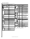
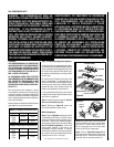
FINISHING REQUIREMENTS
Wall Details
Complete finished interior wall. To install the
appliance facing flush with the finished wall,
position framework to accommodate the thick-
ness of the finished wall (
Figures 59 and 60
)
Step 11. HOOD INSTALLATION
All of these appliances must have hoods
installed on all sides with glass enclosure
panels prior to operating.
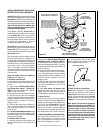
On all clean face units, slide the hoods into the slots
on the lower edges of the radiant panels
(Figure 59)
.
On louvered face units, slide the hoods into the slots
on the lower edges of the cabinet top.
(Figure 60)
.
Note: Combustible wall finish materials and/
or surround materials must not be allowed to
encroach the area defined by the appliance
front face (black sheet metal). Never allow
combustible materials to be positioned in front
of or overlapping the appliance front face. See
Figures 59 or 60.
Non-combustible materials, such as sur-
rounds and other appliance trim, may be
installed on the appliance front face with
these exceptions: they must not cover any
portion of the glass or louvers; they may
cover any portion of the top radiant panel or
the air gaps surrounding the top radiant panel
up to the installed hood.
Vertical installation clearances to combus-
tible mantels vary according to the depth of
the mantel. See
Figure 62
. Mantels con-
structed of non-combustible materials may
be installed at any height above the appliance
opening; however, do not allow anything to
hang below the hood.