


2
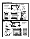
NOTE: DIAGRAMS & ILLUSTRATIONS NOT TO SCALE.
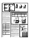
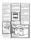
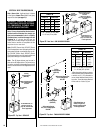
Figure 1
CDPF
CDST
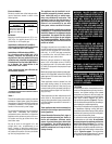
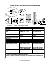
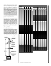
Millivolt Models -
Millivolt models come standard with the
manually-modulated gas valve; flame ap-
pearance and heat output can be con-
trolled at the gas valve.
Input of millivolt models is shown in the
following table:
Electronic appliances are designed to operate
on natural or propane gas. An electronic inter-
mittent pilot ignition system provides safe,
efficient operation. External electrical power is
required to operate these units.
These appliances comply with National Safety
Standards and are tested and listed by War-
nock Hersey (Report No. J20006712) to ANSI
Z21.88-2000 (in Canada, CSA-2.33-2000), and
CAN/CGA-2.17-M91 in both USA and Canada,
as vented gas fireplace heaters.
Both millivolt and electronic versions of these
appliances are listed by Warnock Hersey for
installation in bedrooms and mobile homes.
Installation must conform to local codes. In the
absence of local codes, installation must com-
ply with the current National Fuel Gas Code,
ANSI Z223.1. (In Canada, the current CAN-1
B149 installation code.) Electrical wiring must
comply with the National Electrical Code ANSI/
NFPA 70 - (latest edition). (In Canada, the
current CSA C22-1 Canadian Electrical Code.)
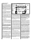
TYPICAL INSTALLATION
DO NOT ATTEMPT TO ALTER OR MODIFY
THE CONSTRUCTION OF THE APPLIANCE OR
ITS COMPONENTS. ANY MODIFICATION OR
ALTERATION MAY VOID THE WARRANTY,
CERTIFICATION AND LISTINGS OF THIS UNIT.
INTRODUCTION
These fireplaces are designed, tested and listed
for operation and installation with, and only with,
Secure Vent™ Direct Vent System Components,
Secure Flex™ Flexible Vent Components manu-
factured by Security Chimneys International and
Z-Flex™ Model GA Venting Systems, listed to
UL1777 and ULCS635 manufactured by Flex-
master Canada Limited. These approved vent
system components are labeled for identifica-
tion. DO NOT use any other manufacturer's vent
components with these appliances.
The millivolt appliances are designed to operate
on either natural or propane gas. A millivolt gas
control valve with piezo ignition system pro-
vides safe, efficient operation. If any optional
accessories which require electrical power are
being installed, the electrical power must be
provided at the time of appliance installation.
GENERAL INFORMATION
Note: Installation and repair should be per-
formed by a qualified service person. The appli-
ance should be inspected annually by a quali-
fied professional service technician. More fre-
quent inspections and cleanings may be re-
quired due to excessive lint from carpeting,
bedding material, etc. It is imperative that the
control compartment, burners and circulating
air passage ways of the appliance be kept clean.
S'assurer que le brùleur et le compartiment des
commandes sont propres. Voir les instruc-
tions d'installation et d'utilisation qui
accompagnent l'appareil.
Provide adequate clearances around air open-
ings and adequate accessibility clearance for
service and proper operation. Never obstruct
the front, back and/or side viewing surfaces of
the appliance.
These appliances are designed to operate on
natural or propane gas only.
This installation manual will help you achieve a
safe, efficient and dependable installation for
your appliance and vent system.
Please read
and understand these instructions be-
fore beginning your installation.
Packaging ........................................ page 2
Introduction ..................................... page 2
General Information......................... page 2
Location .......................................... page 3
Appliance and Vent Clearances....... page 4
Vent Termination Clearances ........... page 4
Typical Installation Sequence .......... page 5
Detailed Installation Steps ............... page 5
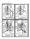
Step 1. Framing ............................. page 5
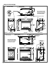
Fireplace Specifications ................... page 8
Step 2. Routing Gas Line ............... page 10
Step 3. Install the Venting System . page 10
Vertical Termination Systems .......... page 11
Vent Section Length Chart ............... page 11
Vertical Vent Tables and Figures...... page 14
Horizontal Termination System........ page 16
Horizontal Vent Tables and Figures . page 18
Venting Using Flexible Vent Pipe ..... page 21
Step 4. Field Wiring ....................... page 22
Step 5. Optional Blower Kit Wiring page 22
Step 6. Connecting Gas Line.......... page 23
Step 7. Installing Logs, Decorative Volcanic
Stone and Glowing Embers ........... page 23
Step 8. Checking Unit Operation ..... page 23
Step 9. Installing Glass
Enclosure Panels ........................... page 24
Step 10. Burner Adjustments........... page 24
Step 11. Hood Installation ............... page 25
Finishing Requirements ................... page 25
Cold Climate Insulation.................... page 25
Installation Accessories ................... page 26
Gas Conversion Kits.................. page 28
TABLE OF CONTENTS
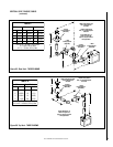
sledoMtlovilliM
enaporPdnalarutaN
sledoMsaG
)H/UTB(etartupnI
-yllaunaM
detaludom
,NMC-FPDC,NMC-TSDC
,NMC-RCDC,NMC-LCDC
,PMC-FPDC,PMC-TSDC
PMC-RCDC,PMC-LCDC
005,73OT000,03
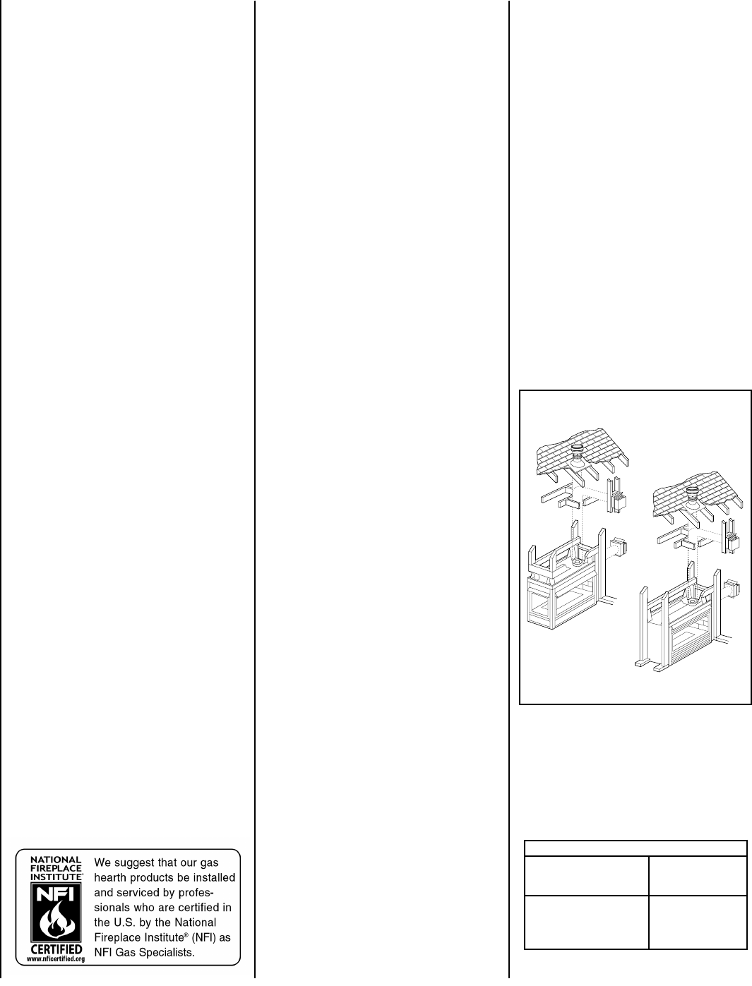
PACKAGING
The assembled vented gas fireplace heater is
packaged with:
1 - one cartoned log set located in firebox area;
decorative volcanic stone and glowing em-
bers (rockwool) located inside the bottom
cabinet compartment.
2 -one envelope containing the literature
package which consists of the homeowner's
manual, installation instructions, warranty,
and 8 (CDST), 4 (CDPF, CDCR and CDCL)
nailing flanges; envelope is located on top
of the unit.
3 - one vent restrictor to be applied as shown on
page 10
; restrictor is taped to the envelope.
4 - two hoods (CDST, CDCR, CDCL), or three
hoods (CDPF) taped to the top of the fireplace.
NOTE: DIAGRAMS & ILLUSTRATIONS NOT TO SCALE.