


24
NOTE: DIAGRAMS & ILLUSTRATIONS NOT TO SCALE.
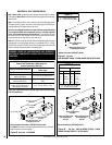
Glass Door
Latch
Control Compartment Access Panel and Hinge
Front Glass
Enclosure Panel
Firebox Floor
Bottom Vee-flange
Glass Door Frame
Top Flange
Glass Door Frame
Modesty Panel
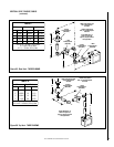
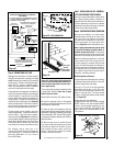
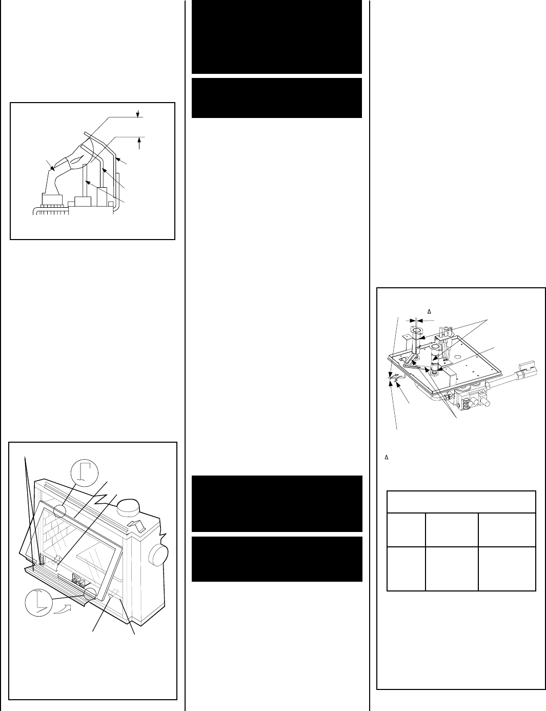
CDST SHOWN
RENRUBNIAM***
GNITTESRETTUHSYROTCAF
sledoM
saGlarutaN
sehcni
)mm(
saGenaporP
sehcni
)mm(
TSDC
FPDC
RCDC
LCDC
OWT*
8/1)3(
STOLS
OWT**
61/11)71(
STOLS
Adjustment Rod Positions (when viewed
from above):
*Natural Gas
- fully clockwise
**Propane
- fully counter clockwise
*** Settings are shown for each burner.
Figure 57
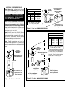
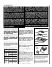
INSTALLING THE GLASS DOOR
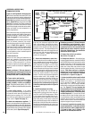
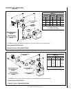
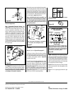
Figure 58
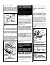
Air Shutter
Adjusting
Rod
Air Shutter
Adjusting
Arms
Orifice
Increase Shutter
Opening In This
Direction
Decrease Shutter
Opening In This
Direction
Air Shutter
Opening
Burner
Venturi
Tube
Note - Both air shutters open and close simultaneously
when the air shutter adjusting rod is moved.
Note - Burners are omitted in this view for clarity.
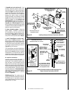
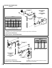
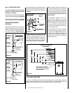
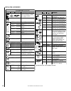
ELECTRONIC
Proper Flame
Adjustment
Pilot
Nozzle
3/8 To 1/2 Inch
(9 mm to 13 mm)
Ground
Electrode
Flame Rod
Hot Surface
Igniter
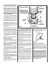
Burner Adjustment
Sooting is indicated by black puffs developing at
the tips of very long orange flames. Sooting
results in black deposits forming on the logs,
appliance inside surfaces and on exterior sur-
faces adjacent to the vent termination. Sooting is
caused by incomplete combustion in the flames
and lack of combustion air entering the air
shutter opening. To achieve a warm yellow to
orange flame with an orange body that does not
soot, the shutter opening must be adjusted
between these two extremes.
No smoke or soot should be present. Reposition
the log set if flames impinge on any part of it.
If the log set is properly positioned and sooting
conditions exist, the air shutter opening on the
main burner tube should be adjusted. Normally,
the more offsets in the vent system, the greater
the need for the air shutter to be opened further.
Allow the burner to operate for at least 15
minutes. Observe the flame continuously. If it
appears weak or sooty as previously described,
adjust the air shutter by rotating the adjust-
ment rod until the flame appearance is as
desired.
Step 10. BURNER ADJUSTMENTS
Flame Appearance and sooting
Proper flame appearance is a matter of taste.
Generally, most people prefer the warm glow of
a yellow to orange flame. Appliances operated
with air shutter openings that are too large will
exhibit flames that are blue and transparent.
These weak, blue and transparent flames are
termed anemic. If the air shutter opening is too
small sooting may occur.
The adjustment rod and associated adjustable air
shutter is patented technology. Flame adjust-
ments can be made quickly and accurately to taste
without the need of disassembling the appliance
and waiting for 15 minutes after each adjustment.
Propane models may exhibit a flame pattern
that may candle or appear stringy. If this is
problematic or persists as the appliance is
continually operated, adjust the air shutter
closed as described in the previous paragraphs.
Operate the appliance for a period of time as the
effect diminishes, ensuring that the appliance
does not develop sooty flames.
When satisfied that the appliance operates prop-
erly, proceed to finish the installation. Leave the
control knob in the ON position and the remote
switch OFF. Close the lower control compart-
ment door.
CAUTION: THE AIR SHUTTER DOOR AND
NEARBY APPLIANCE SURFACES ARE HOT.
EXERCISE CAUTION TO AVOID INJURY WHILE
ADJUSTING FLAME APPEARANCE.
To adjust the flame, rotate the adjustment rod
(located in the lower control area) counterclock-
wise to increase or clockwise to reduce the air
shutter opening. Adjust the air shutter to the
recommended setting as shown in
Figure 58
.
WARNING: HANDLE THE GLASS WITH EX-
TREME CARE! TEMPERED GLASS IS SUS-
CEPTIBLE TO DAMAGE (SCRATCHES, FOR
EXAMPLE) – HANDLE GLASS DOORS
(GLASS ENCLOSURE PANELS) GENTLY
WHILE REINSTALLING THEM.
WARNING: NEVER OPERATE THE APPLIANCE
WITHOUT THE GLASS ENCLOSURE PANELS
IN PLACE AND SECURE.
WARNING: AIR SHUTTER ADJUSTMENT
SHOULD ONLY BE PERFORMED BY A
QUALIFIED PROFESSIONAL SERVICE
TECHNICIAN.
IMPORTANT: ENSURE THAT THE GLASS
ENCLOSURE PANELS ARE IN PLACE
AND SEALED DURING ADJUSTMENT.
Figure 56
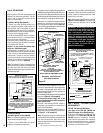
Step 9. INSTALLING GLASS ENCLOSURE
PANELS
Electronic Appliance Checkout
To light the burner, turn ‘ON’ the the wall-
mounted ON/OFF switch or the thermostat
(depending on the type of control installed),
and turn the gas control switch to the “ON”
position. Ensure the ignitor lights the pilot. The
pilot flame should engulf the flame rod as
shown in
Figure 56
.
1. Visually inspect the gasket on the backside
of the panels. The gasket surface must be
clean, free of irregularities and seated firmly.
2. Position the glass enclosure panel in front
of the firebox opening at a 45 degree angle and
engage the top flange over the lip at the top of
the firebox opening.
See Figure 57.
3. Swing the glass enclosure panel down and
back. Ensure the gasket seats evenly as the
panel draws shut. Engage the Vee-flange at
the bottom of the panel with the latches and
close the latches to secure the panel.