


4
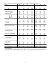
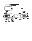
Table 1 - Performance and Dimensional Data - Tubular 30 thru 120 Propeller Unit Heater
Unit Size 30 45 60 75 90 105 120
PERFORMANCE DATA†
Input - BTU/Hr. 30,000 45,000 60,000 75,000 90,000 105,000 120,000
(kW) (8.8) (13.2) (17.6) (22.0) (26.4) (30.8) (34.2)
Output - BTU/Hr. 24,300 36,450 48,600 60,750 72,900 85,050 97,200
(kW) (7.1) (10.7) (14.2) (17.8) (21.4) (24.9) (28.5)
Thermal Effi ciency (%) 81 81 81 81 81 81 81
Free Air Delivery - CFM 370 550 740 920 1,100 1,300 1,475
(cu. m/s) (.175) (.260) (.349) (.434) (.519) (.614) (.696)
Air Temperature Rise - Deg. F 60 60 60 60 60 60 60
(Deg. C) (15) (15) (15) (15) (15) (15) (15)
Full Load Amps at 120V 3.0 3.0 3.7 4.1 6.4 6.4 6.4
Maximum Circuit Ampacity 3.5 3.5 4.4 4.8 7.5 7.5 7.5
MOTOR DATA: Motor HP 1/20 1/20 1/12 1/12 1/10 1/10 1/10
Motor (kW) (0.04) (0.04) (0.06) (0.06) (0.075) (0.075) (0.075)
Motor Type SP SP SP SP SP SP SP
R.P.M. 1650 1650 1050 1050 1050 1050 1050
Motor Amps @ 115V 1.9 1.9 2.6 2.6 4.2 4.2 4.2
DIMENSIONAL DATA - inches (mm)
“A” Jacket Height 12-3/8 12-3/8 15-7/8 15-7/8 22-5/8 22-5/8 22-5/8
(314) (314) (403) (403) (574) (574) (574)
“B” Overall Height 13-1/4 13-1/4 16-13/16 16-13/16 23-9/16 23-9/16 23-9/16
(337) (337) (427) (427) (598) (598) (598)
“C” Overall Depth 25-7/8 25-7/8 26-3/16 26-3/16 26-3/8 26-3/8 26-3/8
(632) (632) (665) (665) (670) (670) (670)
“D1” Center Line Height of Flue* 8-1/2 8-1/2 10-3/8 10-3/8 13-5/8 13-5/8 13-5/8
(216) (216) (263) (263) (346) (346) (346)
“D2” Center Line Height of Air Intake 8-1/2 8-1/2 8 8 8-5/8 8-5/8 8-5/8
(216) (216) (203) (203) (219) (219) (219)
“E” Fan Diameter 10 10 14 14 16 16 16
(254) (254) (356) (356) (406) (406) (406)
“F” Discharge Opening Height 10-13/16 10-13/16 14-7/16 14-7/16 21-3/16 21-3/16 21-3/16
(275) (275) (367) (367) (538) (538) (538)
“G” Vent Connection Diameter 4 4 4 4 4 4 4
(102) (102) (102) (102) (102) (102) (102)
“H1” Center Line of Flue Connection From Side 7-1/4 7-1/4 7-1/4 7-1/4 7-3/4 7-3/4 7-3/4
(184) (184) (184) (184) (197) (197) (197)
“H2” Center Line of Air Intake From Side 2-3/4 2-3/4 2-3/4 2-3/4 3-1/2 3-1/2 3-1/2
(70) (70) (70) (70) (89) (89) (89)
Vent Size Requirements - Standard Combustion
Category I Horizontal** 4 4 4 5 5 5 5
(102) (102) (102) (127) (127) (127) (127)
Category III Horizontal 4 4 4 4 4 4 4
(102) (102) (102) (102) (102) (102) (102)
Category I & III Vertical 4 4 4 4 4 4 4
(102) (102) (102) (102) (102) (102) (102)
Vent Size Requirements - Separated Combustion
Exhaust Diameter** 4 4 4 4 5 5 5
(102) (102) (102) (102) (127) (127) (127)
Intake Air Diameter 4 4 4 4 5 5 5
(102) (102) (102) (102) (127) (127) (127)
Unit Weight - lbs. 57 60 75 87 96 103 112
(kgs) (27) (29) (34) (37) (45) (48) (49)
Shipping Weight - lbs. 67 70 90 96 109 143 152
(kgs) (32) (33) (41) (44) (51) (66) (67)
* For all installations, the fl ue collar is included with the unit and should be fi eld installed per the instructions included with the unit.
** 4-5" reducer supplied where required.
† Ratings shown are for unit installations at elevations between 0 and 2,000 ft (0 to 610m). For unit installations in U.S.A. above 2,000 ft. (610m), the unit input must be derated 4% for each 1,000 ft. (305m) above sea
level; refer to local codes, or in absence of local codes, refer to the latest edition of the National Fuel Gas Code, ANSI Standard Z223.1 (N.F.P.A. No. 54), (also refer to Table 6).