


18
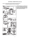
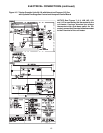
4. Slope horizontal runs upward
from the gas unit heater at least
1/4-inch per foot (21mm/m)
minimum. Horizontal Vent
Connector length should not
exceed 75% of the vertical
height of the vent pipe for single
wall, or 100% of the vertical
height for B-Vent connectors.
Maximum vent connector length
is 10 feet (3m). For exceptions
see Ch. 10 of the National Fuel
Gas Code, ANSI Z223.1.
Horizontal portions of the venting
system shall be supported
at minimum intervals
of
4 feet (1.2m) (in
Canada,
support at
3 foot intervals
(1m)
minimum intervals.
5. Use as few elbows as
possible.
6. Seal all vent pipe joints
and seams to prevent
leakage. Use General
Electric RTV-108, Dow-
Corning RTV-732, or
equivalent silicone
sealant with a temper-
ature rating of 500 deg. F,
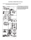
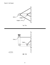
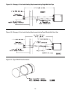
HORIZONTALLY VENTED, CATEGORY I - Figure 13
Observe the following precautions
when venting the unit:
1. Use fl ue pipe of the size shown
on Table 5. All heaters must be
vented with a UL Listed, Type B
or single wall vent. Refer to Table
5 for dimensional restrictions.
2. Each unit must have an
individual vent pipe and vent
terminal. Unit must not be
connected to other vent systems
or to a chimney.
3. A minimum vertical rise is
required for Category I venting.
See Table 5 for specifications.
The vent terminal must be at
least 3 feet (1m) above grade,
or in snow areas, at least 3
feet (1m) above the snow line
to prevent blockage by snow.
Install a weather cap over the
vent opening. An Amerivent
Americap or Metalbestos
vent cap must be supplied by
the customer for each power
vented unit.
4. Through the wall venting for these
appliances shall not terminate
over public walkways, or over an
area where the condensate or
vapor could create a nuisance,
hazard, or could be detrimental to
the operation of regulators, relief
valves, or other equipment.
5. Seal all vent pipe joints and
seams to prevent leakage. Use
General Electric RTV-108, Dow-
Corning RTV-732, or equivalent
silicone sealant with a tempera-
ture rating of 500 deg. F, or 3M
# 425 aluminum foil tape (or
equivalent). The vent system
must be installed to prevent
collection of condensate. Pitch
horizontal pipes downward 1/4
inch per foot (21mm per meter)
toward the outlet for condensate
drainage. Install a tee with a
condensate drain at the low point
of the pipe (see Figure 13). As
an alternate, a 3/8 inch diameter
hole may be drilled at the low
point of the pipe for condensate
drainage.
6. Horizontal portions of the venting
system shall be supported at
minimum intervals of 4 feet (1.2m)
to prevent sagging (in Canada,
support at 3 foot (1m) minimum
intervals).
8. Avoid running vent pipe through
unheated spaces. When this
cannot be avoided, insulate the
pipe to prevent condensation of
moisture on the walls of the pipe.
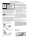
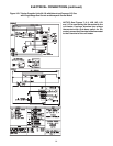
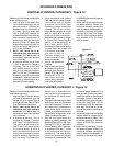
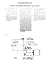
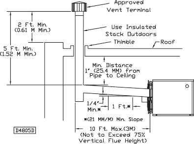
VERTICALLY VENTED, CATEGORY I - Figure 12
Observe the following precautions
when venting the unit:
1. Use flue pipe of the same size
as the fl ue connection(s) on the
gas unit heater 4" (102mm). All
heaters must be vented with a
UL Listed, Type B or single wall
vent, a factory built chimney, or
a lined brick and mortar chimney
that has been constructed in
accordance with the National
Building Code. All tables and
dimensions assume B vent for
the fl ue and single wall pipe or B
vent for the connector.
2. Each unit must have an
individual vent pipe and vent
terminal. Unit must not be
connected to other vent systems
or to a chimney.
3. A minimum vertical rise of 5 feet
(1.5m) is required for Category
I venting. The top of the vent
pipe should extend at least 2
feet (0.61m) above the highest
point on the roof. Consideration
should be made for anticipated
snow depth. Install an Amerivent
Americap or Metalbestos vent
cap over the vent opening.
or 3M #425 aluminum foil tape (or
equivalent).
7. Avoid running vent pipe through
unheated spaces. When this
cannot be avoided, insulate the
pipe to prevent condensation of
moisture on the walls of the pipe.
Insulate vent pipe runs longer
than 10 ft (3m). Insulation should
be a minimum of 1/2" (12.7 mm)
thick foil faced.
Figure 12
STANDARD COMBUSTION