


27
VENTING (continued)
4.
Use single wall pipe constructed of 26 GA galvanized
steel or a material of equivalent durability and corrosion
resistance for the vent system. For installations in
Canada, use
corrosion resistant and gas-tight, listed
vent pipe conforming with local building codes, or
in the absence of local building codes, with current
CAN/CGA-B149.1, Installation Codes for Natural
Gas Burning Appliances and Equipment or CAN/
CGA-B149.2, Installation Codes for Propane Gas
Burning Appliances and Equipment.
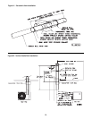
For residential
installations in the United States, vent pipe approved
for Category III appliances must be used between the
appliance and the concentric vent box unless 33% of
the vent run is vertical, then single wall galvanized
vent pipe or double wall Type B vent pipe may be used
between the appliance and the concentric vent box. A
single length of double wall Type B vent pipe must be
used to go through the concentric vent box and outside
wall to the vent terminal.
5. Any run of single wall vent pipe passing through an
unheated space must be insulated with an insulation
suitable to 550° F.
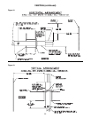
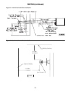
6. The vent system must be installed to prevent
collection of condensate. Pitch horizontal pipes
downward 1/4 inch per foot (21mm per meter) toward
the vent cap to facilitate drainage. Vertical vent pipes
should be piped as depicted in Figure 22.
7. The equivalent length of the vent system must not be
less than 5 feet (1.5m) and must not exceed 30 feet
(9m). The equivalent length equals the total length
of straight pipe plus 5 feet (1.5m) for each 90° elbow
and 2.5 feet (0.76m) for each 45° elbow.
8. Each slip joint must be secured with at
least three corrosion resistant screws.
Two full turns of 3M #425 Aluminum Foil
tape or its equivalent must then be used
to seal each joint. High temperature
silicone sealant may be used instead of
the tape. Silicone sealant must be used
to seal the joint between the Type B vent
pipe and the single wall pipe.
9. For horizontal vent systems longer
than 5 feet (1.5m), the system must
be supported from overhead building
structures at 4 foot (1.2m) intervals in
the U.S. and at 3 foot (0.91m) intervals in
Canada.
10. The exhaust vent system must remain
at a minimum distance of 1 inch (25mm)
from all combustible materials. Any part
of the vent system that passes through
a combustible material must be properly
insulated.
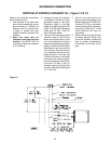
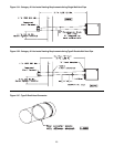
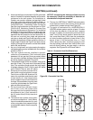
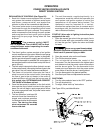
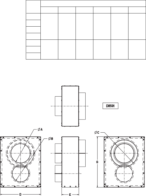
Figure 20 - Concentric Vent Box
NOTICE: Increasing the clearance distances may
be necessary if there is a possibility of distortion or
discoloration of adjacent materials.
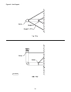
11. The top of a VERTICALLY VENTED exhaust system
must extend at least 3 feet (0.91m) above the roof
surface that it passes through. See Figure 22.
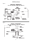
12. The point of termination for a HORIZONTALLY
VENTED exhaust system must be at least 12 inches
(0.3m) from the exterior of the wall that it passes
through. In addition, the termination point must be at
least 1 foot (0.3m) above grade or above the snow
line, more than 6 feet (1.8m) from the combustion
air inlet of another appliance, at least 4 feet (1.2m)
below, 4 feet (1.2m) horizontally from, or 1 foot
(0.3m) above any door, window or gravity air inlet
into any building, and more than 3 feet (0.91m) from
and not directly above, any gas meter or service
regulator. See Figures 23 and 24 and Table 4.
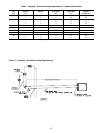
Table 6 - Concentric Vent Box Dimensions
Unit
Dimensions - Inches (Nominal)
Size
A B C D E G
30
45
4
1
/
2
4 6 8 5 12
60
75
90
105 5
1
/
2
5 8 12 5 15
120
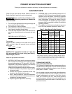
SEPARATED COMBUSTION