


32
PRIMARY AIR SHUTTER ADJUSTMENT
Primary air adjustment is made at the factory. No fi eld adjustments are necessary.
GAS INPUT RATE
Check the gas input rate as follows (Refer to General
Safety Information section for metric conversions).
Never overfi re the unit heater, as this
may cause unsatisfactory operation, or shorten the
life of the heater.
1. Turn off all gas appliances that use gas through the
same meter as the unit heater.
2. Turn the gas on to the unit heater.
3. Clock the time in seconds required to burn 1 cubic
foot of gas by checking the gas meter.
4. Insert the time required to burn one cubic foot of
gas into the following formula and compute the input
rate.
3600 (Sec. per Hr.) X BTU/Cu. Ft.
= Input Rate
Time (Sec.)
For example:
Assume the BTU content of one cubic foot of gas is
1000, and that it takes 48 seconds to burn one cubic
foot of gas.
3600 x 1000
= 75,000
48
NOTICE: If the computation exceeds, or is less than
95% of the gas BTU/hr. input rating (see Table 1),
adjust the gas pressure.
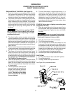
Adjust the gas pressure as follows:
1. NATURAL GAS: Best results are obtained when
the unit heater is operating at its full rated input with
the manifold pressure of 3.5 inches W.C. (0.9 kPa).
Adjustment of the pressure regulator is not normally
necessary since it is preset at the factory.
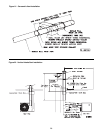
However, fi eld adjustment may be made as follows:
a. Attach manometer at the pressure tap plug below
the control outlet.
b. Remove the regulator adjustment screw cap,
located on the combination gas valve.
c. With a small screwdriver, rotate the adjustment
screw counterclockwise to decrease pressure, or
clockwise to increase pressure.
d. Replace regulator adjustment screw cap.
2. PROPANE GAS: An exact manifold pressure of 10.0
inches W.C. (2.5 kPa) must be maintained for proper
operation of the unit heater. If the unit is equipped
with a pressure regulator on the combination gas
valve, follow steps "a" through "d" above. If the unit
is not so equipped, the propane gas supply system
pressure must be regulated to attain this manifold
operating pressure.
3. The adjusted manifold pressure should not vary more
than 10% from pressure specifi ed in Tables 7 & 8.
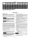
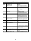
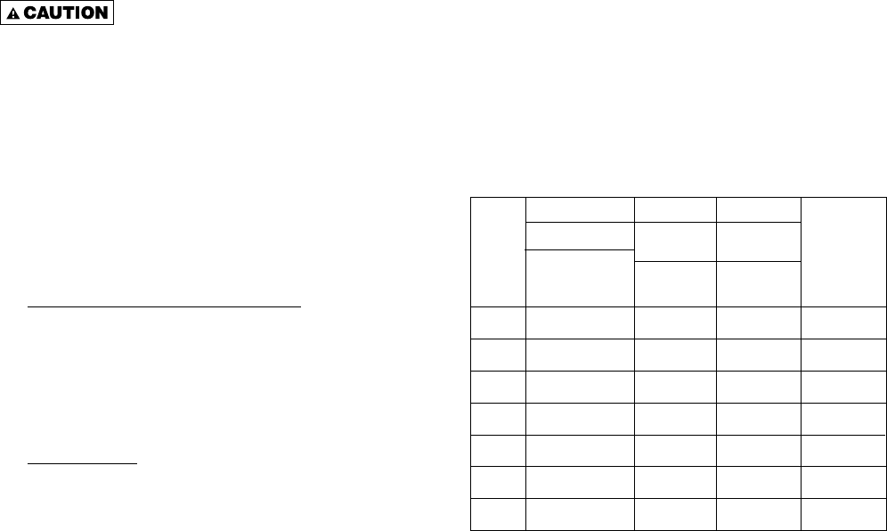
Table 7 - Main Burner Orifi ce Schedule*
TUBULAR UNIT HEATER
HIGH ALTITUDE DERATION
This Tubular Unit Heater has been manufactured utilizing
standard burner orifi ces and a normal manifold pressure
setting as per the specifi cations shown on your unit rating
plate (refer to Tables 3, 7 and 8).
All unit deration must be done through fi eld adjustments
by a qualified technician (refer to Table 8). Once the
proper adjustments are made in the field, attach
label #J17-06459 to the unit, and record adjusted
manifold pressure, altitude of the unit installation and
the technician’s name and date on the label using a
permanent marker.
*
INPUT
IN
1000
BTU
2500 BTU/Ft
3
(93.1 MJ/m
3
)
PROPANETYPE OF GAS NATURAL
1075 BTU/Ft
3
(40.1 MJ/m
3
)
3.5" W.C.
(0.87kPA)
10" W.C.
(2.49 kPA)
NO. OF
BURNER
ORIFICES
MANIFOLD
PRESSURE
1
1
1
1
1
1
1
30
45
60
75
90
105
120
FT
3
/HR
ORIFICE DRILL
FT
3
/HR
ORIFICE DRILL
FT
3
/HR
ORIFICE DRILL
FT
3
/HR
ORIFICE DRILL
FT
3
/HR
ORIFICE DRILL
FT
3
/HR
ORIFICE DRILL
FT
3
/HR
ORIFICE DRILL
28
38
42
1/8
56
27
70
20
84
16
98
11
112
5
12
52
18
48
24
42
30
37
36
35
42
31
48
1/8
HEATING VALUE
*This schedule is for units operating at normal altitudes of 2000 ft. (610m)
or less.
When installed in Canada, any references to deration at altitudes in excess
of 2000 ft. (610m) are to be ignored. At altitudes of 2000 to 4500 ft. (610 to
1372m), the unit heaters must be orifi ced to 90% of the normal altitude rating,
and be so marked in accordance with ETL certifi cation.