


8
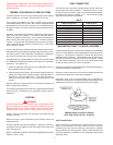
TABLE 3
EQUIVALENT LENGTH OF FITTINGS IN FEET
Pipe Size (IPS) 1 1.25 1.5 2 2.5 3 4
Std. Tee through side 5.5 7.5 9.0 12.0 14.0 17.0 22.0
Std. E11 2.7 3.7 4.3 5.5 6.5 8.0 12.0
45°F E11 1.2 1.6 2.0 2.5 3.0 3.7 5.0
Plug Cock 3.0 4.0 5.5 7.5 9.0 12.0 16.0
WARNING
THE HEATER IS NOT INTENDED FOR OPERATION AT HIGHER
THAN 13.8” WATER COLUMN (1/2 POUND PER SQUARE INCH)
SUPPLY GAS PRESSURE. HIGHER GAS PRESSURE
REQUIRES SUPPLEMENTAL REDUCING SERVICE
REGULATION. EXPOSURE TO HIGHER GAS SUPPLY
PRESSURE MAY CAUSE DAMAGE TO THE GAS CONTROLS
WHICH COULD RESULT IN FIRE OR EXPLOSION. IF
OVERPRESSURE HAS OCCURRED SUCH AS THROUGH
IMPROPER TESTING OF GAS LINES OR EMERGENCY
MALFUNCTION OF THE SUPPLY SYSTEM, THE GAS VALVE
MUST BE CHECKED FOR SAFE OPERATION. MAKE SURE
THAT THE OUTSIDE VENTS ON THE SUPPLY REGULATORS
AND THE SAFETY VENT VALVES ARE PROTECTED AGAINST
BLOCKAGE. THESE ARE PARTS OF THE GAS SUPPLY
SYSTEM, NOT THE HEATER. VENT BLOCKAGE MAY OCCUR
DURING ICE STORMS.
IT IS IMPORTANT TO GUARD AGAINST GAS VALVE FOULING
FROM CONTAMINANTS IN THE GAS WAYS. SUCH FOULING
MAY CAUSE IMPROPER OPERATION, FIRE OR EXPLOSION.
IF COPPER SUPPLY LINES ARE USED THEY MUST BE
INTERNALLY TINNED AND CERTIFIED FOR GAS SERVICE.
BEFORE ATTACHING THE GAS LINE, BE SURE THAT ALL GAS
PIPE IS CLEANED ON THE INSIDE.
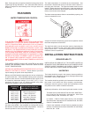
TO TRAP ANY DIRT OR FOREIGN MATERIAL IN THE GAS
SUPPLY LINE, A DIRT LEG (SOMETIMES CALLED A SEDIMENT
TRAP OR DRIP LEG) MUST BE INCORPORATED IN THE
PIPING. THE DIRT LEG MUST BE READILY ACCESSIBLE AND
NOT SUBJECT TO FREEZING CONDITIONS. INSTALL IN
ACCORDANCE WITH RECOMMENDATIONS OF SERVING GAS
SUPPLIERS. REFER TO THE
NATIONAL FUEL GAS CODE.
To prevent damage, care must be taken not to apply too much
torque when attaching gas supply pipes to gas valve inlet.
Apply joint compounds (pipe dope) sparingly and only to the male
threads of pipe joints. Do not apply compound to the first two
threads. Use compounds resistant to the action of liquefied
petroleum gases.
DISCONNECT THE APPLIANCE AND ITS MANUAL GAS
SHUTOFF VALVE FROM THE GAS SUPPLY PIPING SYSTEM
DURING ANY SUPPLY PRESSURE TESTING EXCEEDING
1/2 PSIG. GAS SUPPLY LINE MUST BE CAPPED WHEN
DISCONNECTED FROM THE HEATER. FOR TEST
PRESSURES OF 1/2 PSIG OR LESS, THE APPLIANCE NEED
NOT BE DISCONNECTED, BUT MUST BE ISOLATED FROM
THE SUPPLY PRESSURE TEST BY CLOSING THE MANUAL
GAS SHUTOFF VALVE.
BEFORE PLACING THE HEATER IN OPERATION, CHECK FOR
GAS LEAKAGE. USE SOAP AND WATER SOLUTION OR
OTHER MATERIAL ACCEPTABLE FOR THE PURPOSE OF
LOCATING GAS LEAKS. DO NOT USE MATCHES, CANDLES,
FLAME OR OTHER SOURCES OF IGNITION FOR THIS
PURPOSE.
PURGING
Gas line purging is required with new piping or systems in which
air has entered.
CAUTION
PURGING SHOULD BE PERFORMED BY PERSONS
EXPERIENCED IN THIS TYPE GAS SERVICE. TO AVOID RISK
OF FIRE OR EXPLOSION, PURGE DISCHARGE MUST NOT
ENTER CONFINED AREAS OR SPACES WHERE IGNITION
CAN OCCUR. THE AREA MUST BE WELL VENTILATED AND
ALL SOURCES OF IGNITION MUST BE INACTIVATED OR
REMOVED.
GAS METER SIZE – CITY GASES ONLY
Be sure that the gas meter has sufficient capacity to supply the
full rated gas input of the water heater as well as the requirements
of all other gas fired equipment supplied by the meter. If gas
meter is too small, request the gas company to install a meter
having adequate capacity.
GAS PRESSURE REGULATOR
DO NOT SUBJECT COMBINATION GAS VALVE TO INLET GAS
PRESSURE OF MORE THAN 14 I.W.C. A SERVICE
REGULATOR IS NECESSARY IF HIGH GAS PRESSURES ARE
ENCOUNTERED.
The gas pressure regulator vent line must be vented to the
outside of the building.
POWER BURNER
For information relating to the power burner supplied with this
water heater, refer to the power burner manual provided.
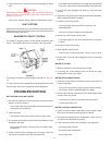
LIFTING LUGS
This water heater is supplied with lifting lugs. Prior to lifting, insure
that the lugs are threaded into their receptacles as tight as
possible.
These lugs may be removed after installation. Sheet metal covers
are provided to cover the receptacle openings.
WIRING
The rating plate provides the electrical information needed to size
the water heater branch supply circuit.
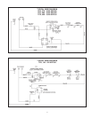
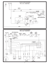
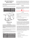
Typical water heater electrical diagrams are provided in this
manual (pages 9 and 10). The actual diagram, corresponding to
each water heater, is provided with each water heater, and may
differ from the diagrams shown in this manual.
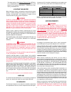
The TPG unit burner is wired to the water heater control
compartment as shown in the following diagram. The electrical
service should be connected to the N & L Terminals located in
the control compartment. Ground from control compartment to
suitable ground.
All electrical work must be installed in accordance with the
National
Electrical Code (latest version) and local requirements. AN
ELECTRICAL GROUND IS REQUIRED TO REDUCE THE RISK
OF ELECTRICAL SHOCK. DO NOT ENERGIZE THE BRANCH
CIRCUIT BEFORE THE HEATER TANK IS FILLED WITH
WATER.