


5
The latest version of the National Electrical Code, NFPA No.
70. In Canada refer to Canadian Electrical Code C 22.1, from
National Fire Protection Association, 1 Batterymarch Park,
Quincy, MA 02269-9101.
LOCATING THE HEATER
When installing the heater, consideration must be given to proper
location. Location selected should be as close to the stack or
chimney as practicable, with adequate air supply and as
centralized with the piping system as possible.
WARNING
THERE IS A RISK IN USING FUEL BURNING APPLIANCES
SUCH AS GAS WATER HEATERS IN ROOMS, GARAGES OR
OTHER AREAS WHERE GASOLINE, OTHER FLAMMABLE
LIQUIDS OR ENGINE DRIVEN EQUIPMENT OR VEHICLES ARE
STORED, OPERATED OR REPAIRED. FLAMMABLE VAPORS
ARE HEAVY AND TRAVEL ALONG THE FLOOR AND MAY BE
IGNITED BY THE HEATER’S IGNITION SYSTEM OR MAIN
BURNER FLAMES CAUSING FIRE OR EXPLOSION.
SOME LOCAL CODES PERMIT OPERATION OF GAS
APPLIANCES IF INSTALLED 18 INCHES OR MORE ABOVE THE
FLOOR. THIS MAY REDUCE THE RISK IF LOCATION IN SUCH
AN AREA CANNOT BE AVOIDED.
THE HEATER SHALL BE LOCATED OR PROTECTED SO IT IS
NOT SUBJECT TO PHYSICAL DAMAGE BY A MOVING
VEHICLE.
WARNING
FLAMMABLE ITEMS, PRESSURIZED CONTAINERS OR ANY
OTHER POTENTIAL FIRE HAZARDOUS ARTICLES MUST
NEVER BE PLACED ON OR ADJACENT TO THE HEATER.
OPEN CONTAINERS OF FLAMMABLE MATERIAL SHOULD
NOT BE STORED OR USED IN THE SAME ROOM WITH THE
HEATER.
THE HEATER MUST NOT BE LOCATED IN AN AREA WHERE
IT WILL BE SUBJECT TO FREEZING.
LOCATE HEATER NEAR A FLOOR DRAIN. THE HEATER
SHOULD BE LOCATED IN AN AREA WHERE LEAKAGE FROM
THE TANK OR CONNECTIONS WILL NOT RESULT IN DAMAGE
TO THE ADJACENT AREA OR TO LOWER FLOORS OF THE
STRUCTURE.
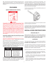
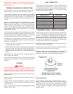
WHEN SUCH LOCATIONS CANNOT BE AVOIDED, A SUITABLE
METAL DRAIN PAN, ADEQUATELY DRAINED, SHOULD BE
INSTALLED UNDER THE HEATER. Such pans should be
fabricated with sides at least 2” deep, with length and width at
least 2” greater than the diameter of the heater and must be piped
to an adequate drain. The pan must not restrict combustion air
flow.
This unit must be installed on a non-combustible surface.
LEVELING
The heater shall be installed level. If it is necessary to adjust the
heater, use metal shims under the channel-type skid base.
CLEARANCES
Provide ample clearance on all sides for installation, adjustment
and replacement of burner, control components and other parts.
A clearance of 24” should be maintained from serviceable parts,
such as relief valve, power burner, thermostat and drain valve.
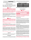
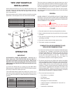
MINIMUM INSTALLATION CLEARANCES
TPG/TPX TPO/TPD
FRONT - 18 Inches FRONT - 18 Inches
BACK - 0 Inches Back - 6 Inches
TOP - 5 Inches Top - 12 Inches
LEFT SIDE - 0 Inches LEFT SIDE - 6 Inches
RIGHT SIDE - 0 Inches RIGHT SIDE - 6 Inches
NOTE: If a chimney connector is used, the minimum clearance
from the top of the unit to the connector is 18 inches.
AIR REQUIREMENTS
WARNING
FOR SAFE OPERATION, AN AMPLE SUPPLY OF AIR MUST
BE PROVIDED FOR PROPER COMBUSTION AND
VENTILATION AIR IN ACCORDANCE WITH SECTION 5.3, AIR
FOR COMBUSTION AND VENTILATION, OF THE
NATIONAL
FUEL GAS CODE, NFPA-54/ANSI Z223.1 OR APPLICABLE
PROVISIONS OF THE LOCAL BUILDING CODES. AN
INSUFFICIENT SUPPLY OF AIR WILL RESULT IN A YELLOW,
LUMINOUS BURNER FLAME, CAUSING CARBONING OR
SOOTING OF THE HEAT EXCHANGER AND CREATING A RISK
OF ASPHYXIATION. DO NOT OBSTRUCT THE FLOW OF
COMBUSTION AND VENTILATION AIR.
UNCONFINED SPACE
In buildings of conventional frame, brick or stone construction,
unconfined spaces may provide adequate air for combustion.
If the unconfined space is within a building of tight construction
(buildings using the following construction: weather stripping,
heavy insulation, caulking, vapor barrier, etc.), air for combustion,
ventilation and draft hood dilution must be obtained from outdoors
or spaces freely communicating with the outdoors. The installation
instructions for confined spaces in tightly constructed buildings
must be followed to ensure adequate air supply.
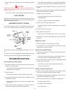
CONFINED SPACE
When drawing combustion and dilution air from inside a
conventionally constructed building to a confined space, such a
space shall be provided with two permanent openings, ONE IN
OR WITHIN 12 INCHES OF THE ENCLOSURE TOP AND ONE
IN OR WITHIN 12 INCHES OF THE ENCLOSURE BOTTOM.
Each opening shall have a free area of at least one square inch
per 1000 Btu/hr of the total input of all appliances in the enclosure,
but not less than 100 square inches.
If the confined space is within a building of tight construction, air
for combustion, ventilation and draft dilution must be obtained
from outdoors. When directly venting with the outdoors or venting
with the outdoors through vertical ducts, two permanent openings,
located in the aforementioned manner, shall be provided. Each
opening shall have a free area of not less than one square inch
per 4000 Btu/hr of the total input of all appliances in the enclosure.
If horizontal ducts are used, each opening shall have a free area
of not less than one square inch per 2000 Btu/hr of the total input
of all appliances in the enclosure.
Where an exhaust fan is installed in the same room with the boiler,
sufficient openings for air must be provided in the walls.
UNDERSIZED OPENINGS WILL CAUSE AIR TO BE DRAWN
INTO THE ROOM THROUGH THE CHIMNEY OR OTHER