


6
UNDESIRABLE OPENINGS, CAUSING POOR COMBUSTION.
SOOTING MAY RESULT WITH AN INCREASED RISK OF
ASPHYXIATION.
THERMAL EXPANSION (CLOSED SYSTEM)
Thermal expansion occurs in any hot water system when system
water is heated or “recovered” during periods of non-use.
If the system is operated in an “open” condition such as being
connected directly to the city main, the volume of expanded water
generated during the recovery periods can be dissipated back
through the “open” connection to the city main so pressure cannot
increase.
However, once a back flow preventer is installed to isolate system
water from the public supply; or a pressure reducing valve is
installed to protect a water meter; or any device preventing flow
back into the cold water supply, the “open” condition becomes
“closed”. During periods of temperature recovery and no usage,
water expands and the pressure increases until a relief valve
opens spilling hot water.
A relief valve opening on pressure will flow small amounts of water,
whereas relieving on temperature releases large amounts of water.
Consult the section under “High Water Temperature” to determine
the cause of the relief valve to open due to temperature.
Since the water is not compressible, some provision must be made
for THERMAL EXPANSION to protect the system from excessive
pressures. Two options are:
1. Install an expansion tank properly and adequately sized for
the expanding volume of water.
2. Install a pressure relief valve in the cold water supply line having
a setting of at least 10lbs.
below the system working pressure,
located at or near a suitable drain. This valve will open at
each heat cycle when there is no hot water demand on the
system.
Service problems or parts failure due to excessive pressure are
NOT covered under warranty.
The pressure and temperature relief valve supplied with the water
heater
IS NOT considered to be protection against thermal
expansion.
VENTING
WARNING
THE INSTRUCTIONS IN THIS SECTION ON VENTING MUST
BE FOLLOWED TO AVOID CHOKED COMBUSTION OR
RECIRCULATION OF FLUE GASES. SUCH CONDITIONS
CAUSE SOOTING OR RISKS OF FIRE AND ASPHYXIATION.
Heater must be protected from freezing downdrafts during
shutdown periods.
Remove all soot or other obstructions from chimney, which will
retard free draft.
Venting materials used for this category 1 appliance must be in
accordance with the National Fuel Gas Code and all state and
local requirements.
NOTE: A NEGATIVE DRAFT MUST BE MAINTAINED IN VENT
PIPING (-0.02 to -0.06).
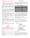
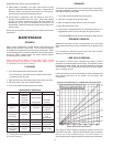
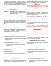
VENT CONNECTOR
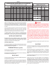
The chimney vent connector diameter should be the same size
as the heater flue outlet, see table 1. A minimum rise of 1/4” per
foot of horizontal connector length must be maintained between
the heater and chimney opening, fig. 2. The connector length
should be kept as short as possible.
TABLE 1
TPG/TPX/TPO/TPD FLUE OUTLET
INPUT (KBTUh) (INCHES)
140, 199 5
255, 270, 300 6
400 7
540, 600 8
720, 800, 1000 10
1250, 1500 12
1750, 2000 14
2250, 2500 16
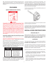
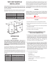
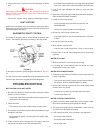
BAROMETRIC DRAFT CONTROL ASSEMBLY
A double-acting barometric draft control assembly is provided with
each unit. This assembly must be attached to the heater as shown
in figure 2. The direction in which the outlet to the draft control
assembly faces is arbitrary. This assembly must be fitted to the
jacket cover such that it is plumb and level to the ground. Fasten
the draft control assembly to the top cover using sheet metal
screws at three locations, or more, as required.
Refer to the instructions provided with the barometric damper for
complete installation requirements.
Dampers or other obstructions must not be installed between the
heater and the barometric draft control assembly.
Barometric draft control counterweights can be adjusted for
installation conditions by an authorized State Start-Up Agent. Any
readjustment must be by authorized State Start-Up agent.
PROPER DRAFT CONTROLLER AND
VENT PIPE INSTALLATION - FIGURE 2
VENT CONNECTION
Vent connections must be made to an adequate stack or chimney.
Refer to the National Fuel Gas Code or to the vent pipe
manufacturer’s gas vent and chimney sizing table to properly
design and size the venting system. Refer to Table 2 for the vent
pipe size required for installation to the barometric draft control
assembly outlet.